
Building the OrBlink USB RGB LED
This is the guide to building the OrBlink USB RGB LED Kit.
You'll need a few tools which aren't included in the kit. To assemble the board you'll need a soldering iron, some solder, some wire strippers and some small wire cutters. To pull apart and put together the orb you'll need a large flat head screwdriver (or a coin), a small phillips screwdriver, and a drill or something else to make a hole. Other useful items are a helping hand tool to hold the board while you solder which will make things much easier and a good multimeter to test your joints but they aren't strictly necessary.
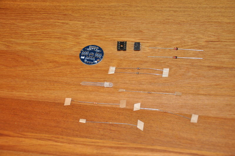
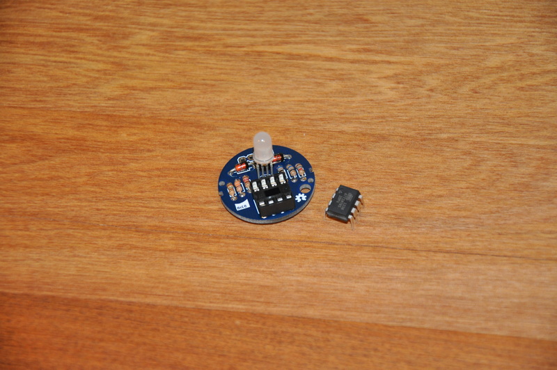
Step 1. Check the parts, you should have the following;
- 1 Orb
- 1 OrBlink PCB
- 1 Pre-programmed ATTiny85 microcontroller
- 1 DIP socket for the microcontroller
- 1 RGB LED
- 2 Zener diodes (D1,D2)
- 1 220 ohm resistor (R1 - red red brown)
- 1 330 ohm resistor (R2 - orange orange brown)
- 1 150 ohm resistor (R3 - brown green brown)
- 2 68 ohm resistors (R4,R5 - blue grey black)
- 1 1.8k ohm resistor (R6 - brown grey red)
- 1 USB Cable
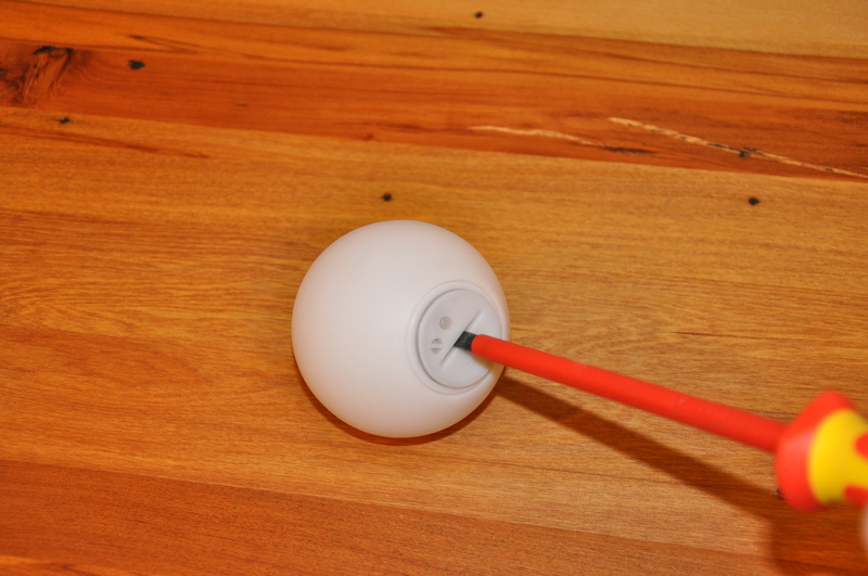
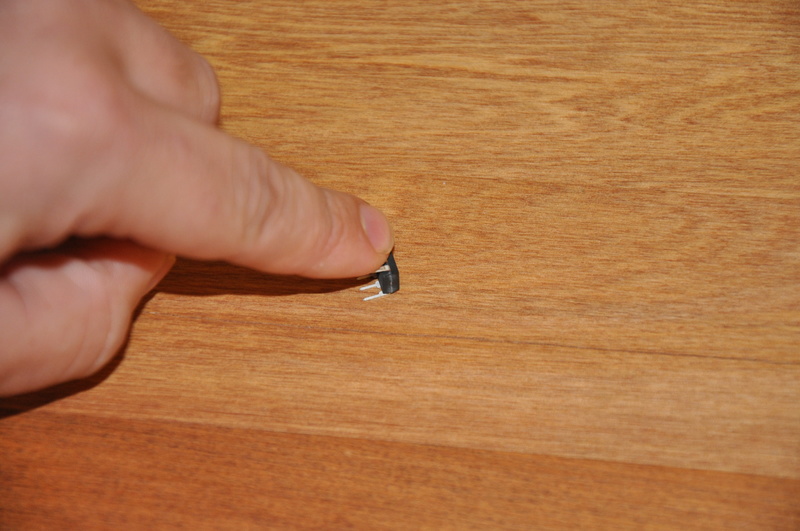
Step 2. Remove the base of the orb, it's best to use a coin here or a really big flat head screwdriver - they tend to be pretty tight.
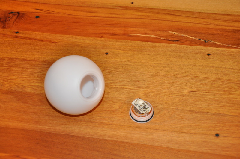
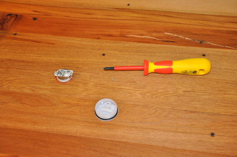
Step 3. Remove the old PCB and battery assembly from the orb. Save the screws, do whatever you like with the old PCB.
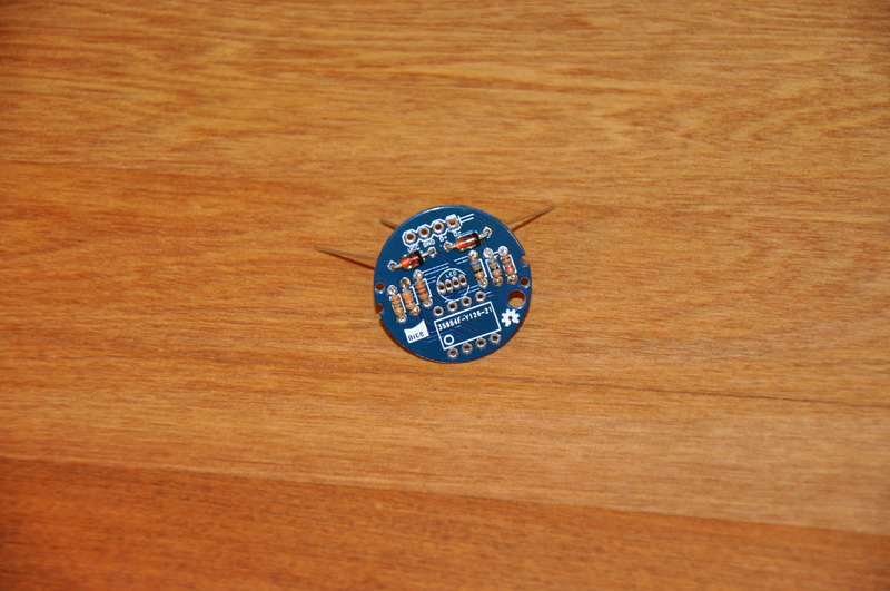
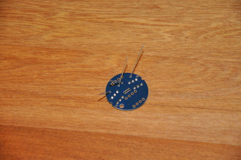
Step 4. Install R1 (220 ohms, red red brown), R2 (330 ohms, orange orange brown) and R3 (150 ohms, brown green brown). Bend the legs, insert them through the holes and bend as per the picture to hold them in while you solder.
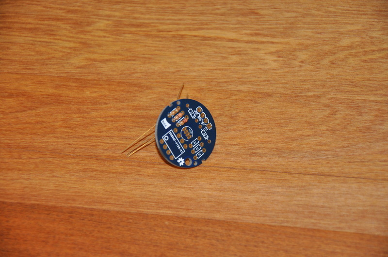

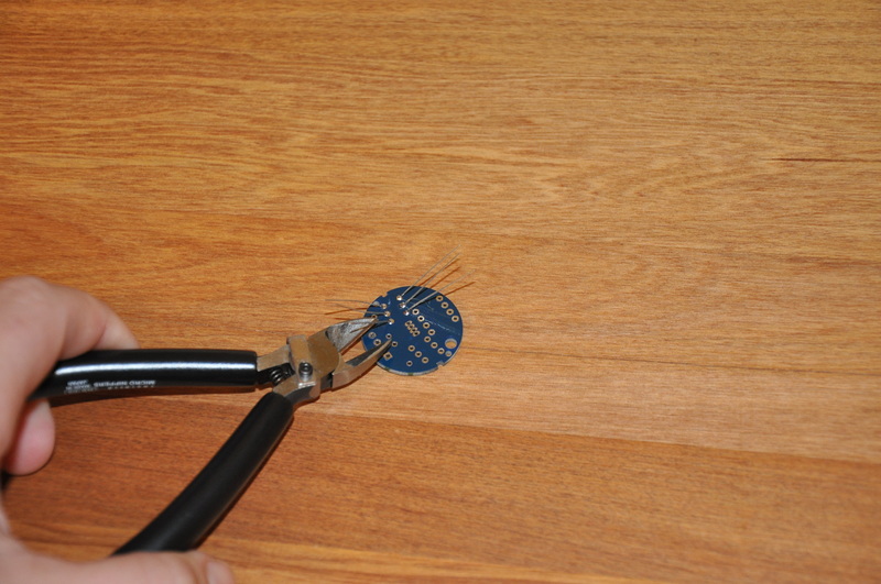
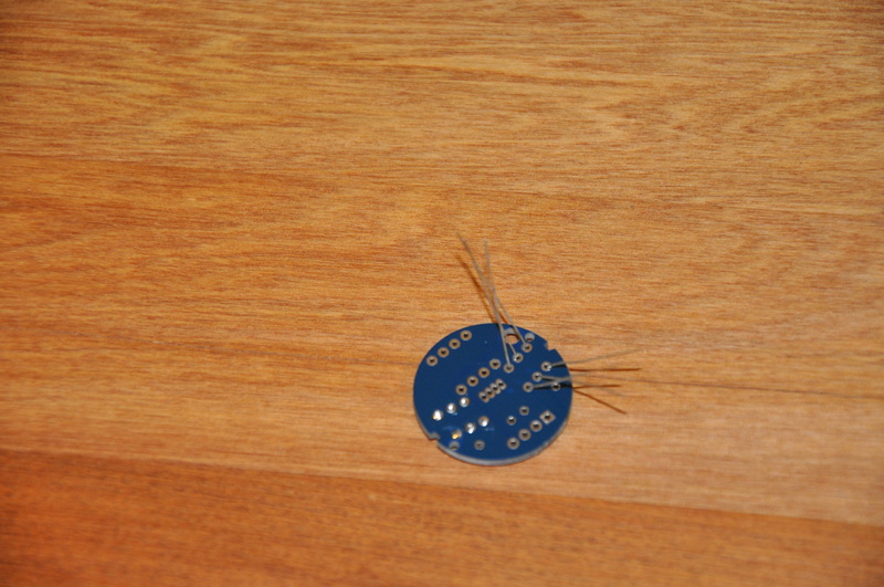
Step 5. Solder the resistors by touching each lead with the soldering iron a piece of solder lightly. Trim off the leads with your flush cutters.
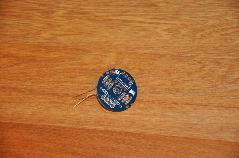
Step 6. Install R4, R5 (68 ohm blue grey black) and R6 (1.8k ohm brown grey red) using the same technique as above.
Step 7. Install the zener diodes using the same technique as the resistors above. Be careful as diodes are polarised - you need to install the stripe to match the stripe on the PCB.
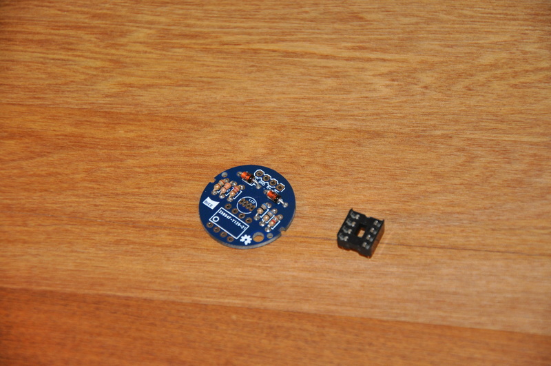
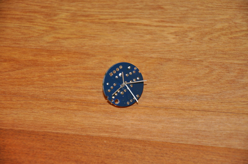
Step 8. Solder in the DIP socket, orient it so that the end with the notch cut out is at the same end as the small circle pin 1 marker on the PCB.

Step 8. Place the RGB LED through the PCB, leave it sticking up around 15mm so it doesn't cast shadows of the other components on the inside of the orb. Orient the LED so the flat side of the plastic is facing towards R4.

Step 9. Solder in the LED. Use a little solder here as the pads are quite close together and may bridge if you use too much.
Step 10. Install the ATTiny85 microcontroller, if you need to you can bend the legs in slightly by pressing down on a flat surface. The end with the little round impression on the top goes at the end of the socket with the notch in it.
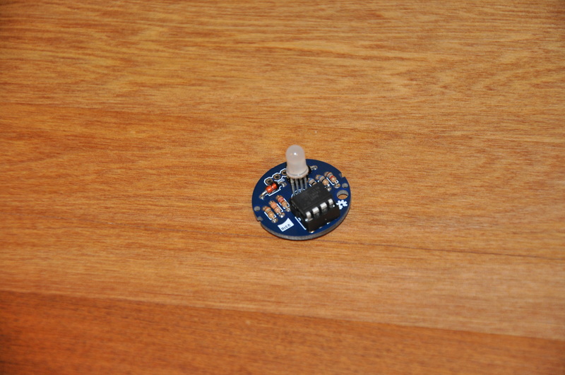
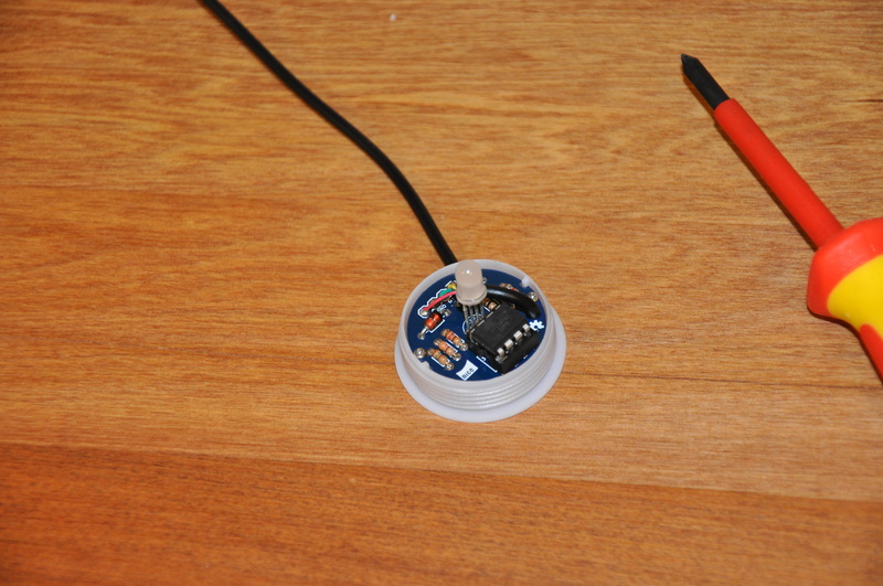
Step 11. That's the PCB assembly completed, well done! Now you just need to put the orb back together.
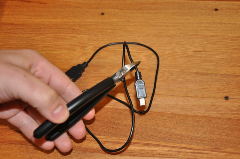
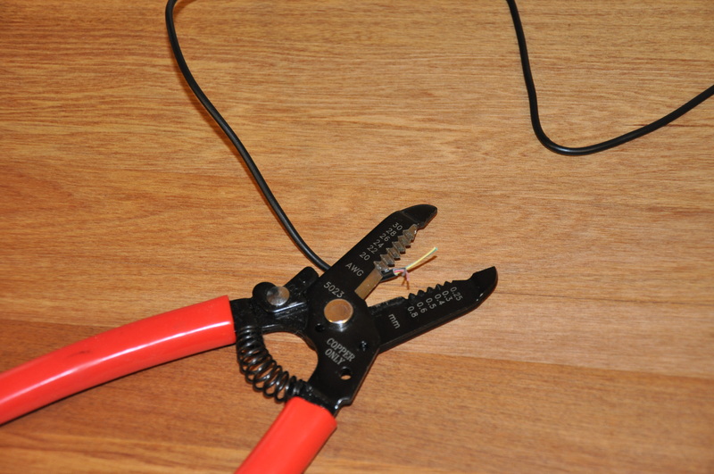
Step 12. Cut the end off the USB cable (not the one that plugs into the computer) and strip the large outer insulation, then the four smaller wires inside that. You only need a short amount os the inner insulation stripped.
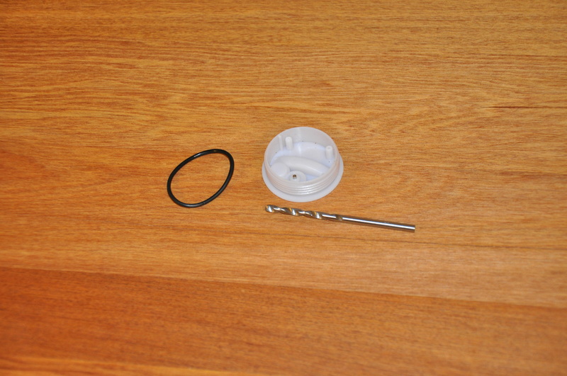
Step 13. Remove the rubber gasket from around the orb base and drill a small hole in the very bottom of the thread. It needs to be big enough to fit the USB cable, around 3mm.
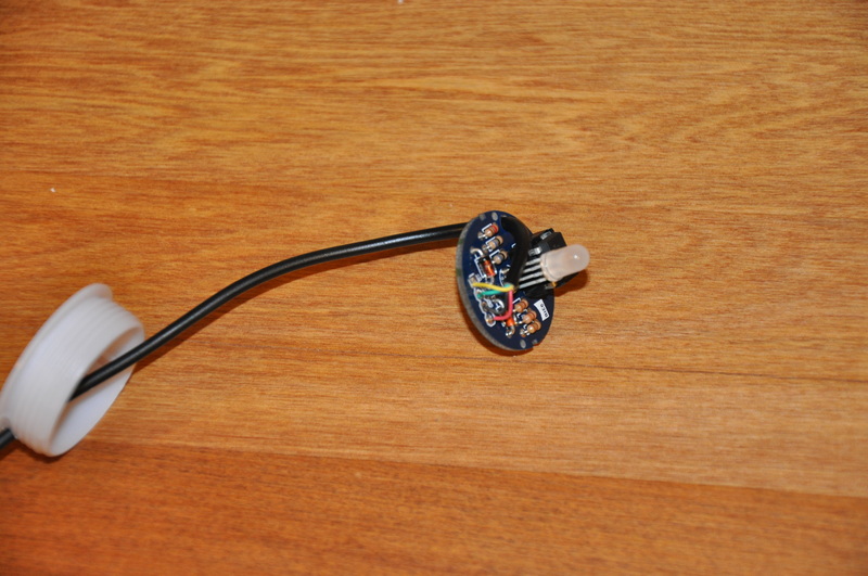
Step 14. Insert the stripped end of the cable through the orb base and the large hole in the PCB.
Step 15. Solder the stripped wires into the PCB, most USB cables use standard colors. Red for 5V, black for ground, green for D+ and yellow for D- match them up to the labels on the PCB.
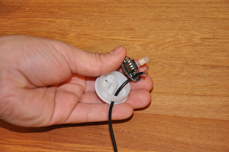
Step 16. Screw the newly completed OrBlink PCB into the existing holes in the orb base with the screws you saved from the start.
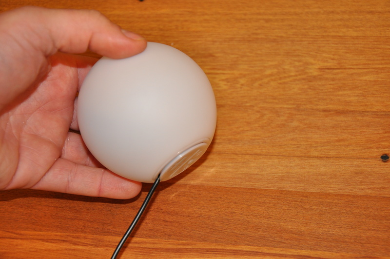
Step 17. Screw the base back on to the orb, plug the OrBlink into your computer and start making colors!
If you're new to soldering you might want to test the USB cable to make sure there aren't any shorts which may cause damage to your computers USB port. This is up to you.