
Hacking a Mitsubishi Heat Pump / Air Conditioner
Quite a few years back I decided that I wanted to hack my heat pump. The infrared remote control was boring, who wants to press buttons. I thought about automatically generating the infrared remote button protocol like a few others have done before but that still doesn't tell me what the heat pump is doing. Did it actually turn on after you sent those commands? I thought I could do better, so I decided to pull apart my newly installed heat pump unit and start poking around in there with a meter to see what happened.
Surprisingly, I remembered to take a couple of photos this time Here's the unit after pulling off the cover and poking around to find where all the wires were going. Try not to die if you do this with the power on - there's 240V in there.
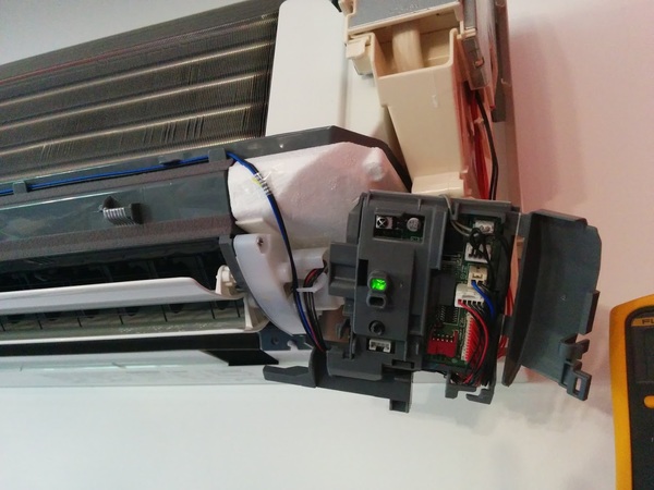
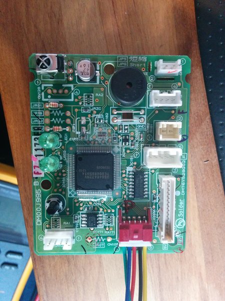
Here I've pulled out the control board. Tiny little thing isn't it! You'll see one of the wiring looms connected here, this is what we need to connect to communicate with the unit from the outside world - thoughtfully of them they made us a serial port to talk to, it's 5V TTL UART running at 2400 bps and even parity. A little weird, I discovered that with a Saleae Logic Analyser - a very handy little hacking tool. The connector is called CN105 on the Mitsubishi board.
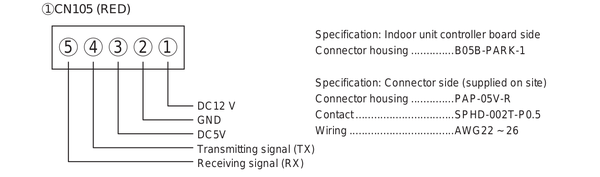
After I had manually poked about and figured out the CN105 pin output and discovered it was a UART, I found this picture of the pinout of the Mitsubishi CN105 connector! Would have been nice to have earlier! Posted here in case you're building your own cable. The original cable I built was actually a JST PH connector that I carved and sanded to fit in the existing PCB end - figuring out what type of connector was on the board was one of the most annoying parts of the whole thing! I've since discovered (after extensive searching!) that it's a JST PA series and I do have a few cable pigtails here so if you want one drop me a line.
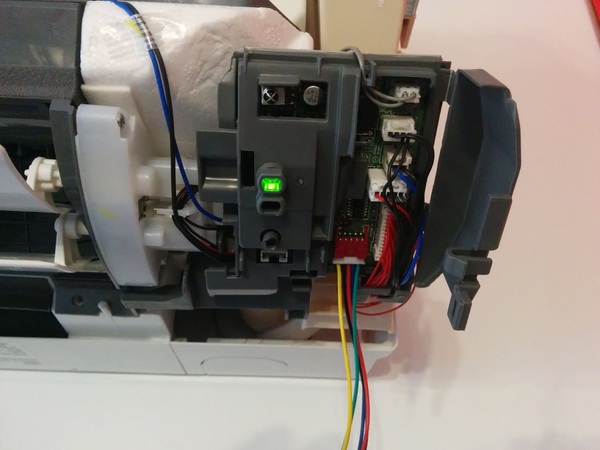
At this stage I'm putting the control board assembly back into the heat pump and connecting it back up to all the factory wiring looms. Once of those is the internal temperature sensor with I did some testing on sensor as part of trying to decode the communications protocol - I think I'll go into the protocol in a separate post to keep this from getting too long.
Once I got the air conditioning unit back together it was time to implement the hack in a reusable manner. I decided to base my modification on a Raspberry Pi. I could have gone with something smaller such as an Arduino, or an ESP8266 board but I decided to go with the Pi as it would give the ability to relatively easily build a completely stand alone controller for people who don't have an existing home automation controller to interface with.
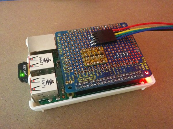
Above is the simple Raspberry Pi break out board mounted on a Raspberry Pi. The couple I have running (one in the office and one at home) are both running on a Raspberry Pi 2 as this was all done before the release of the Pi 3 with built in WiFi. It should work on the Pi 3 okay but I've not tested it as yet and there is a change in the Pi UART due to the on board Bluetooth. I guess it should still be able to handle 2400 bps okay but if you test it out let me know!
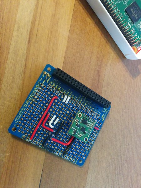
This is just the bottom of the prototype board with some hook up wiring and a 12V to 5V converter from Pololu to power the Pi. The heat pump has a 12V output on the CN105 connector so there's no external power needed for the Raspberry Pi. There's also a 5V supply on the connector but I wasn't sure how much I could draw from that so I decided it was safer to use the 12V rail.
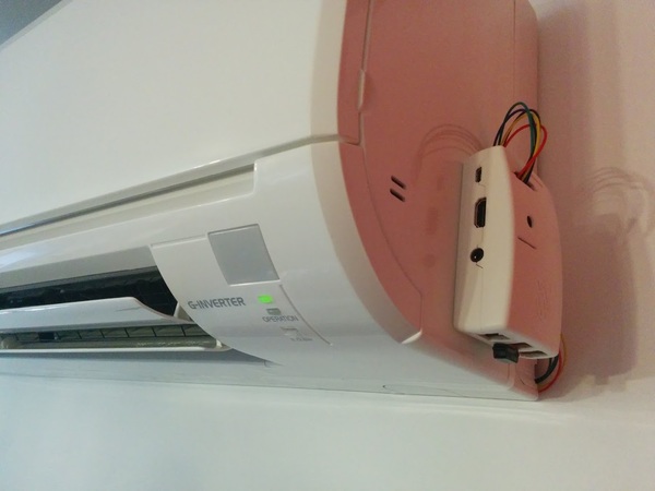
Here's the final prototype that's running in my office. The wiring isn't the tidiest but that's probably inconsequential when you look at the rest of the office most of the time! I won't include a photo of that.
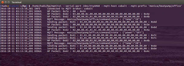
This is the console output from the program which bridges the Mitsubishi Air Conditioner / Heat Pump to an MQTT broker. The code is up on Github here, there's not a lot of documentation but you should be able to get something working from it.
This is a simple control interface in HTML using MQTT over websockets, we use this in house as part of a larger system. I haven't had a chance to extract this bit of code yet.
Update, as usual I forgot to mention a bunch of things : This is true bi-directional communication with the heat pump, meaning that you can send it commands and get back a response on whether they succeeded. The heat pump will also send unsolicited updates when things change such as using the IR remote. This means that the network interface will always be in sync with what the air conditioner unit is actually doing, no guesswork.
There's a bunch of documentation to do on this project which I've currently run out of time for - though I do hope to be able to pick it up again soon. The next post I hope to do is on decoding the serial line communication protocol. If you've got any questions let me know in the comments.
I'd be curious to know more about the protocol in your up and coming post.
With the way things are here in NZ with regard to exporting power to the grid (Eg. from solar PVs) it makes sense to consume all the excess power your house generates. Being able to talk directly with the heat pump is one way to 'suck up' all this excess. I guess it will come down to the protocol as to whether you would have to 'ride' the temperature setting in order to achieve this. I suspect heat pumps some time in the future will let you specify how much power they should consume. This would be beneficial for those with air-water heat pumps with large storage capacity. In this case being able to adjust on a minute by minute basis how much power the heat pump is consuming would be a real bonus.
If I go with Mitsubishi, then I plan to install ESP8266 units and write INO code based on your GIT with MQTT. If I do, do this, I will share somehow.
My ultimate goal is to have one temp sensor per room and have a central MQTT server control hydronic zone valves or mini splits depending on season. Temp settings will be set via web page, no ugly thermostats in any rooms. Just small concealed MQTT tmp sensors.
Regards
-AL
Thanks & Regards
-AL (Chicago)
I was able to write code for sending changes. I have not tested it yet, as my unit is not installed yet. But raw print over serial to my PC shows correct data and chksum byte. Question, what are info packets? I see in your python script that you send it and it has some sort of enumerator that resets periodically. How and when is this used. Last, does the heat pump send packets after something is sent(ack) or does it on its own periodically send packets of its state(I can setup a read interrupt for that)
Let me know if you prefer I ask questions via Email. I think I am pretty close to have converted the code.
Thanks & Regards
-AL (Chicago)
Have you got a link to your code online? I'd be interested in having a look and I'm sure others would too.
Cheers,
Hadley
Again, what are info packets and when are they used? This is the only thing I don't have yet.
Currently my code will send connect packets and command packet to change settings. I have not coded the reader or info packets.
CHeers
-AL
Cheers
-AL
How are you going sharing the code?
I removed the link to your air conditioning service website, I'm guessing that's directly related to why you posted that you should call a service person...
Hadley
https://nicegear.co.nz/wishlists/354
My overambitious dream is to hack a Nest to control my unit, without needing to buy Mitsubishi's over expensive adapter dongle (PAC-US444CN-1). That's super expensive with 2 units. My reason for wanting Nest, instead of any of the other IR automation, or cloud thermostats is because my energy provider offers $25/season for allowing them to control/avoid rush hour energy, which only Nest provides.
ANYWAY, my real question is... how did you go about reverse engineering their UART command set? Does it require to tell the unit actual temperatures, or just to turn on the heating/cooling and then turn it off like a normal thermostat? I can't quite tell from your code, since I'm not very familiar with Python (mostly just C++/lower level instructions). I think I keep getting confused between your data structures for controlling the unit and receiving network packets.
I'm also worried that Mitsubishi may have changed their command structure since you've bought yours, and I may have to re-discover it myself : P
Thanks for being the only one on the Internet to share a project like this!
Most all of the recent units here (New Zealand / Australia) should all use the same serial command set. However I have no idea whether the models sold in North America are the same sadly.
The reason I guess that they all use the same command set is that Mitsubishi here sell a WiFi control system, which from the installation manual online uses the same port therefore the same UART. It's compatible with quite a bunch of units according to their website, and I'd think at least on this side of the world, that they wouldn't change it all of a sudden as it would then be incompatible.
I spent a long while looking at the UART with a logic analyser, figuring out what changed in the data stream when changing things with the IR remote. From what changed, what didn't and they way things changed I figured out the packet length, data bits, checksum position and calculation etc. It was relatively intensive work.
Cheers,
Hadley
I have a 6 zone setup consisting of 4 MSZ-FH units and 2 SEZ-KD. I bought one of the Wifi KUMO clouds and I see that it sends over and over again connect calls, but they change each time. They seem all start with the same set and then send two similar longer sets. I stopped it after a while to see the output, but I am assuming different connect sets until the unit responds to the one that matches it (hence wide support).
Here is what it printed out
5a01 3002 c38a 01c2 a8c3 bc5a 0130 02c3 8a01 c2a8 c3bc
5a01 3002 c38a 01c2 a815 35c3 bf0b 1409 15c3 bfc3 bc5a 0130 02c3 8a01 c2a8 c3bc
5a01 3002 c38a 01c2 a8c3 bc5a 0130 02c3 8a01 c2a8 0b15 0b35 c3bf 150c c3bf c3bc
5a01 3002 c38a 01c2 a8c3 bc5a 0130 02c3 8a01 c2a8 c3bc
5a01 3002 c38a 01c2 a80b 15c3 bf0b 15c3 bf0b 14c3 bc5a 0130 02c3 8a01 c2a8 c3bc
5a01 3002 c38a 01c2 a8c3 bc5a 0130 02c3 8a01 c2a8 0b15 c3bf 0b2c c3bf 0b2d c3bc
5a01 3002 c38a 01c2 a8c3 bc5a 0130 02c3 8a01 c2a8 c3bc
5a01 3002 c38a 01c2 a815 2cc3 bf15 15c3 bf0b 15c3 bc5a 0130 02c3 8a01 c2a8 c3bc
5a01 3002 c38a 01c2 a8c3 bc5a 0130 02c3 8a01 c2a8 1715 c3bf 0b15 c3bf 151d c3bf c3bc
5a01 3002 c38a 01c2 a8c3 bc5a 0130 02c3 8a01 c2a8 c3bc
5a01 3002 c38a 01c2 a817 2c15 2dc3 bf15 15c3 bc5a 0130 02c3 8a01 c2a8 c3bc
5a01 3002 c38a 01c2 a8c3 bc5a 0130 02c3 8a01 c2a8 0515 0b2c 0f25 c3bc
Repeats sets of codes over and over
I am most likely going to have to connect a sniffer while it is connected to the actual unit, or make a sort of relay. And see which code it stops on until my unit is connected.
It looks like connect is sent twice and then a 3rd time with extra data. I never saw any repeats in the extra data, so I don't know if it is junk or a code to ask exactly what the unit is. I plan to hack in all these codes and see when the unit responds to my device.
fc5a013002ca01a8
fc5a013002ca01a8
fc5a013002ca01a80b2c0d2d152cff
fc5a013002ca01a8
fc5a013002ca01a8
fc5a013002ca01a815150d14ff172cff
fc5a013002ca01a8
fc5a013002ca01a8
fc5a013002ca01a81515ff15150b14
fc5a013002ca01a8
fc5a013002ca01a8
fc5a013002ca01a80b0dff0b15ff0d0c
fc5a013002ca01a8
fc5a013002ca01a8
fc5a013002ca01a80b15ff172c1735ff
fc5a013002ca01a8
fc5a013002ca01a8
fc5a013002ca01a80b2dff1714ff0b2cff
fc5a013002ca01a8
fc5a013002ca01a8
fc5a013002ca01a80b2dff0b2dff152d
fc5a013002ca01a8
fc5a013002ca01a8
fc5a013002ca01a8152cff0b1d0b1d
fc5a013002ca01a8
fc5a013002ca01a8
fc5a013002ca01a8152dff0b2c0b15ff
fc5a013002ca01a8
fc5a013002ca01a8
fc5a013002ca01a80b15ff0b2c0f34
fc5a013002ca01a8
fc5a013002ca01a8
fc5a013002ca01a80b15ff152d150cff
fc5a013002ca01a8
fc5a013002ca01a8
fc5a013002ca01a81314ff1b150514ff
fc5a013002ca01a8
fc5a013002ca01a8
fc5a013002ca01a80b15ff17350b2cff
fc5a013002ca01a8
fc5a013002ca01a8
fc5a013002ca01a8152cff0d150d2c
fc5a013002ca01a8
fc5a013002ca01a8
fc5a013002ca01a80b2d1515ff0b15
fc5a013002ca01a8
fc5a013002ca01a8
fc5a013002ca01a80b2dff0b15ff0b15
fc5a013002ca01a8
fc5a013002ca01a8
fc5a013002ca01a8152cff1d15ff0b14ff
fc5a013002ca01a8
fc5a013002ca01a8
fc5a013002ca01a80314ff0b15ff0b2cff
fc5a013002ca01a8
fc5a013002ca01a8
fc5a013002ca01a80b14ff152cff1515ff
fc5a013002ca01a8
fc5a013002ca01a8
fc5a013002ca01a815150b15ff0b15ff
fc5a013002ca01a8
fc5a013002ca01a8
fc5a013002ca01a8132dff09151315ff
fc5a013002ca01a8
fc5a013002ca01a8
fc5a013002ca01a80d15ff15150b2cff
fc5a013002ca01a8
fc5a013002ca01a8
fc5a013002ca01a80b14ff1515ff152dff
fc5a013002ca01a8
fc5a013002ca01a8
fc5a013002ca01a81b15ff0b2cff0b14ff
fc5a013002ca01a8
fc5a013002ca01a8
fc5a013002ca01a8151dff15151534ff
fc5a013002ca01a8
fc5a013002ca01a8
fc5a013002ca01a8152dff0b15ff0b1dff
fc5a013002ca01a8
fc5a013002ca01a8
fc5a013002ca01a8132cff152dff0b2cff
fc5a013002ca01a8
fc5a013002ca01a8
fc5a013002ca01a81515152dff152dff
fc5a013002ca01a8
fc5a013002ca01a8
fc5a013002ca01a81515ff072cff0b15ff
fc5a013002ca01a8
fc5a013002ca01a8
fc5a013002ca01a81b150b2d0b2c
fc5a013002ca01a8
fc5a013002ca01a8
fc5a013002ca01a8150c0b2d0f2c
fc5a013002ca01a8
fc5a013002ca01a8
fc5a013002ca01a81915ff0b2c1315
fc5a013002ca01a8
fc5a013002ca01a8
fc5a013002ca01a81514172dff0b14ff
fc5a013002ca01a8
fc5a013002ca01a8
fc5a013002ca01a8152c1515152c
fc5a013002ca01a8
fc5a013002ca01a8
fc5a013002ca01a815151515ff1524
fc5a013002ca01a8
fc5a013002ca01a8
fc5a013002ca01a8152dff0d15ff1515ff
fc5a013002ca01a8
fc5a013002ca01a8
fc5a013002ca01a81715ff1b15ff0b2cff
fc5a013002ca01a8
fc5a013002ca01a8
fc5a013002ca01a80b15ff0b15ff0b15ff
fc5a013002ca01a8
fc5a013002ca01a8
fc5a013002ca01a80b150b15ff0b2dff
fc5a013002ca01a8
fc5a013002ca01a8
fc5a013002ca01a815140b2c0b2c
fc5a013002ca01a8
fc5a013002ca01a8
fc5a013002ca01a80b350b14152cff
fc5a013002ca01a8
fc5a013002ca01a8
fc5a013002ca01a80b15ff132cff1515ff
fc5a013002ca01a8
fc5a013002ca01a8
fc5a013002ca01a815150b35ff0b0cff
fc5a013002ca01a8
fc5a013002ca01a8
fc5a013002ca01a80b15ff1515092cff
fc5a013002ca01a8
fc5a013002ca01a8
fc5a013002ca01a815151315ff1525ff
fc5a013002ca01a8
fc5a013002ca01a8
fc5a013002ca01a81f140b15ff1714ff
fc5a013002ca01a8
fc5a013002ca01a8
fc5a013002ca01a81715ff0f15ff0b2dff
fc5a013002ca01a8
fc5a013002ca01a8
fc5a013002ca01a80b150f0dff0d15ff
fc5a013002ca01a8
fc5a013002ca01a8
fc5a013002ca01a80b150515ff0b15ff
fc5a013002ca01a8
fc5a013002ca01a8
fc5a013002ca01a80b15ff0b2dff1515
fc5a013002ca01a8
fc5a013002ca01a8
fc5a013002ca01a8151cff0b35ff0b14
fc5a013002ca01a8
fc5a013002ca01a8
fc5a013002ca01a817140b150b14
fc5a013002ca01a8
fc5a013002ca01a8
fc5a013002ca01a80b15ff0b15153d
fc5a013002ca01a8
fc5a013002ca01a8
fc5a013002ca01a80b15ff13150335ff
fc5a013002ca01a8
fc5a013002ca01a8
fc5a013002ca01a8152d0b15ff1515ff
fc5a013002ca01a8
fc5a013002ca01a8
fc5a013002ca01a8152d1515ff1915ff
fc5a013002ca01a8
fc5a013002ca01a8
fc5a013002ca01a8050dff1504ff152dff
fc5a013002ca01a8
fc5a013002ca01a8
fc5a013002ca01a8152cff0b15ff1f15ff
fc5a013002ca01a8
fc5a013002ca01a8
fc5a013002ca01a815150915ff0b15ff
fc5a013002ca01a8
fc5a013002ca01a8
fc5a013002ca01a80b2c0b2dff1115ff
fc5a013002ca01a8
fc5a013002ca01a8
fc5a013002ca01a80915ff152cff1515ff
fc5a013002ca01a8
fc5a013002ca01a8
fc5a013002ca01a80b14ff0b15152c
fc5a013002ca01a8
fc5a013002ca01a8
fc5a013002ca01a80d140b2dff151dff
fc5a013002ca01a8
fc5a013002ca01a8
fc5a013002ca01a815150b15ff152d
fc5a013002ca01a8
fc5a013002ca01a8
fc5a013002ca01a8152c172cff0b15
fc5a013002ca01a8
fc5a013002ca01a8
fc5a013002ca01a80b15ff151cff1515ff
fc5a013002ca01a8
fc5a013002ca01a8
fc5a013002ca01a8152dff0b2cff1715ff
fc5a013002ca01a8
fc5a013002ca01a8
fc5a013002ca01a80b2dff1515ff0b25
fc5a013002ca01a8
fc5a013002ca01a8
fc5a013002ca01a8092cff0b150f2dff
fc5a013002ca01a8
fc5a013002ca01a8
fc5a013002ca01a8152cff0b2cff1515ff
fc5a013002ca01a8
fc5a013002ca01a8
fc5a013002ca01a81134ff0b15ff0d15ff
fc5a013002ca01a8
fc5a013002ca01a8
fc5a013002ca01a8152c0b2c152c
fc5a013002ca01a8
fc5a013002ca01a8
fc5a013002ca01a8132c092c0b2d
fc5a013002ca01a8
fc5a013002ca01a8
fc5a013002ca01a80b2c0b15ff0b2d
fc5a013002ca01a8
fc5a013002ca01a8
fc5a013002ca01a8152cff0b14ff0b14ff
fc5a013002ca01a8
fc5a013002ca01a8
fc5a013002ca01a8172cff0b2c0d2c
fc5a013002ca01a8
fc5a013002ca01a8
fc5a013002ca01a8172cff15150b04
fc5a013002ca01a8
fc5a013002ca01a8
fc5a013002ca01a80b2dff0b2dff0b2dff
fc5a013002ca01a8
fc5a013002ca01a8
fc5a013002ca01a813151b2dff152d
fc5a013002ca01a8
fc5a013002ca01a8
fc5a013002ca01a80b25ff0b2dff1535ff
fc5a013002ca01a8
fc5a013002ca01a8
fc5a013002ca01a8152c1514ff1515ff
fc5a013002ca01a8
fc5a013002ca01a8
fc5a013002ca01a80b2d03151325
fc5a013002ca01a8
fc5a013002ca01a8
fc5a013002ca01a80b150b2cff0b2cff
fc5a013002ca01a8
fc5a013002ca01a8
fc5a013002ca01a8152dff152cff0b2c
fc5a013002ca01a8
fc5a013002ca01a8
fc5a013002ca01a80b15ff15151514
fc5a013002ca01a8
fc5a013002ca01a8
fc5a013002ca01a80b2dff092d1725ff
fc5a013002ca01a8
fc5a013002ca01a8
fc5a013002ca01a81515152cff152cff
fc5a013002ca01a8
fc5a013002ca01a8
fc5a013002ca01a8152cff0715ff1515ff
fc5a013002ca01a8
fc5a013002ca01a8
fc5a013002ca01a80b2dff0b1cff152c
fc5a013002ca01a8
fc5a013002ca01a8
fc5a013002ca01a8132cff0b15ff0b2d
fc5a013002ca01a8
fc5a013002ca01a8
fc5a013002ca01a80b15ff0b15ff0b2dff
fc5a013002ca01a8
fc5a013002ca01a8
fc5a013002ca01a80b15ff1515ff0b15ff
fc5a013002ca01a8
fc5a013002ca01a8
fc5a013002ca01a80b15ff0b15ff0b15ff
fc5a013002ca01a8
fc5a013002ca01a8
fc5a013002ca01a80b2cff152cff0b0cff
fc5a013002ca01a8
fc5a013002ca01a8
fc5a013002ca01a8152cff152cff0b15ff
fc5a013002ca01a8
fc5a013002ca01a8
fc5a013002ca01a80f2dff151cff0b15ff
fc5a013002ca01a8
fc5a013002ca01a8
fc5a013002ca01a81525ff0b25ff152c
fc5a013002ca01a8
fc5a013002ca01a8
fc5a013002ca01a81525ff0b15ff0b25
fc5a013002ca01a8
fc5a013002ca01a8
fc5a013002ca01a80b15ff0b15ff0d2dff
fc5a013002ca01a8
fc5a013002ca01a8
fc5a013002ca01a815150d14ff0b2dff
fc5a013002ca01a8
fc5a013002ca01a8
fc5a013002ca01a8152cff152cff0b15ff
fc5a013002ca01a8
fc5a013002ca01a8
fc5a013002ca01a8151517150b15ff
fc5a013002ca01a8
fc5a013002ca01a8
fc5a013002ca01a80b15ff0b15ff0b0cff
fc5a013002ca01a8
fc5a013002ca01a8
fc5a013002ca01a80b15ff1315ff0b15ff
fc5a013002ca01a8
fc5a013002ca01a8
fc5a013002ca01a80b15ff0b15ff0b15ff
fc5a013002ca01a8
fc5a013002ca01a8
fc5a013002ca01a815150b15ff0b2cff
fc5a013002ca01a8
fc5a013002ca01a8
fc5a013002ca01a80b2dff1514ff152cff
fc5a013002ca01a8
fc5a013002ca01a8
fc5a013002ca01a80b15ff1515ff0b15ff
fc5a013002ca01a8
fc5a013002ca01a8
fc5a013002ca01a80b15ff0b2dff152c
fc5a013002ca01a8
fc5a013002ca01a8
fc5a013002ca01a80915ff0b2dff0b15ff
fc5a013002ca01a8
fc5a013002ca01a8
fc5a013002ca01a80b2cff0b15ff1515
fc5a013002ca01a8
fc5a013002ca01a8
fc5a013002ca01a8151d1515ff1515ff
fc5a013002ca01a8
fc5a013002ca01a8
fc5a013002ca01a80d1cff0915ff0b2cff
fc5a013002ca01a8
fc5a013002ca01a8
fc5a013002ca01a815150b2c0b2dff
fc5a013002ca01a8
fc5a013002ca01a8
fc5a013002ca01a8152c172c0314
fc5a013002ca01a8
fc5a013002ca01a8
fc5a013002ca01a80b15ff15150d2dff
fc5a013002ca01a8
fc5a013002ca01a8
fc5a013002ca01a8152d1515ff152dff
fc5a013002ca01a8
fc5a013002ca01a8
fc5a013002ca01a80b2dff0b24ff1515ff
fc5a013002ca01a8
fc5a013002ca01a8
fc5a013002ca01a80b15ff1515ff0b2cff
fc5a013002ca01a8
fc5a013002ca01a8
fc5a013002ca01a80b15ff15140b15
fc5a013002ca01a8
fc5a013002ca01a8
fc5a013002ca01a80b15ff1515ff0b15ff
fc5a013002ca01a8
fc5a013002ca01a8
fc5a013002ca01a81515ff1515ff0b2cff
fc5a013002ca01a8
fc5a013002ca01a8
fc5a013002ca01a8132c0b2cff0b25ff
fc5a013002ca01a8
fc5a013002ca01a8
fc5a013002ca01a80b150b2c0b2c
fc5a013002ca01a8
fc5a013002ca01a8
fc5a013002ca01a80b15ff0b15ff1515ff
fc5a013002ca01a8
fc5a013002ca01a8
fc5a013002ca01a80b15ff1535ff152d
fc5a013002ca01a8
fc5a013002ca01a8
fc5a013002ca01a8152dff0b15ff0b2cff
fc5a013002ca01a8
fc5a013002ca01a8
fc5a013002ca01a81515ff0b2cff0b15ff
fc5a013002ca01a8
fc5a013002ca01a8
fc5a013002ca01a80b15ff172cff1b25ff
fc5a013002ca01a8
fc5a013002ca01a8
fc5a013002ca01a8152dff0b2dff1515ff
fc5a013002ca01a8
fc5a013002ca01a8
fc5a013002ca01a80b2d1715ff0b2dff
fc5a013002ca01a8
fc5a013002ca01a8
fc5a013002ca01a80b15ff0b2dff0b2dff
fc5a013002ca01a8
fc5a013002ca01a8
fc5a013002ca01a80b15ff0b151515
fc5a013002ca01a8
fc5a013002ca01a8
fc5a013002ca01a80b35ff0b15ff152cff
fc5a013002ca01a8
fc5a013002ca01a8
fc5a013002ca01a80b15ff0b2cff0b15ff
fc5a013002ca01a8
fc5a013002ca01a8
fc5a013002ca01a81735ff152cff1315ff
fc5a013002ca01a8
fc5a013002ca01a8
fc5a013002ca01a81b2dff1515ff0b15ff
fc5a013002ca01a8
fc5a013002ca01a8
fc5a013002ca01a81715ff0b2dff152cff
fc5a013002ca01a8
fc5a013002ca01a8
fc5a013002ca01a80b0cff0b15ff1515ff
fc5a013002ca01a8
fc5a013002ca01a8
fc5a013002ca01a80b2dff0b15ff0b15ff
fc5a013002ca01a8
fc5a013002ca01a8
fc5a013002ca01a813150b15ff151cff
fc5a013002ca01a8
fc5a013002ca01a8
fc5a013002ca01a8112d0b2dff0b2dff
fc5a013002ca01a8
fc5a013002ca01a8
fc5a013002ca01a81515ff0b2cff1335ff
fc5a013002ca01a8
fc5a013002ca01a8
fc5a013002ca01a80b2cff1515ff0b2cff
fc5a013002ca01a8
fc5a013002ca01a8
fc5a013002ca01a81514ff0b14ff152dff
fc5a013002ca01a8
fc5a013002ca01a8
fc5a013002ca01a80b15ff1315ff1715ff
I am unsure if the UART on CN105 is 3.3v ttl or 5v? I am not using or am familiar with the raspberry pi. I only connected a 5v ttl usb to serial convertor on the receive line as I was unsure of the UART voltage level of the Mitsubishi board.
Does a connect byte array need to be issued to see any data? I can't quite understand the python github as I am not a programmer only a hack, but from what I can understand it looks like when the Heat pump object is initiated it calls self.start_packet = Packet.build(0x5a, [0xca, 0x01]). Is this required to see any data on the serial stream?
I can confirm your code works with US models. I guess the reason the ESP8266 did not work, is logic level. It accepts 5V, but only sends 3.3V. In the world of TTL 3.3V is still supposed to be a logical 1 for 5V logic, but I guess Mitsu is a bit more sensitive. I don't have a logic level converter yet, so can't confirm if my C code works yet. But I did hook up a USB 5V UART and used linux to give it a test drive. I made a few small changes, to work with my version of py-serial, but all in all it works as expected.
Hi Matt,
The UART talks 2400,8,E,1 and yes the connect must be sent in order to get an initial HP feedback. There after the info packets must be periodically sent in order to get updates from the HP. For example, I commented out the part that would send the wanted changes to the HP, only info packets sent. Playing with remote and I get its settings. Turn on the wanted send portion and anything I do with the remote, gets over written ;) Kiddy lockout is how I look at that LoL.
Also, pay close attention to the pin config of cn105, on our HPs you will see near cn105 a 1 and 5 in a circle, those correspond to pin1 and pin5.
For your USB UART
Pin1 12V (leave disconnected)
Pin2 GND (connect to GND or G, depending on model)
Pin3 5V (leave disconnected)
Pin4 TX (connect to RX)
Pin5 RX (connect to TX)
If either of you want to discuss with me, my E -mail is a l (at) s w i c a g o . c o m remove spaces ;)
Thanks for confirming it works with US models. It should co-exist with the IR remote fine, we occasionally use the remote in the house here and the code doesn't overwrite what is set from there. You might have changed that in your version.
Hi Matt,
AL answered your question but yes you do need to send the connect and info packets, you can't send more than one per second or the HP won't respond to them.
The HP UART is 5V and the Pi is 3.3V so you need a level shifter in between those.
Cheers,
Hadley
Great news my code for Arduino works...just not yet on ESP, but at least the C code on a arduino micro and yun works. the esp8266 either needs pull ups on TX and RX, possible a level shifter and maye also have to do Serial.swap (reverses RX and TX) so that ESP boot message isn't sent to heat pump.
I have not setup a git yet for this, but I posted working code here
http://www.esp8266.com/viewtopic.php?f=29&t=13207
Regards
-AL
I have created an Arduino library. I added it to my post on esp8266.com
http://www.esp8266.com/viewtopic.php?f=29&t=13207
ToDo: Add the info packet sender, in order to get heat pump responses.
Great work! Thanks for sharing your port. That's really neat, I was considering coding it originally for an ESP8266 but decided on the Pi as I wanted a change from what I'd been doing and could allow people without an existing home automation solution to build something all-in-one with the Pi.
Cheers,
Hadley
https://github.com/SwiCago/HeatPump.git
As long as you can pass Serial or Serial1 it will work. Boards that do not implement HardwareSerial are not supported.
Cheers
-AL
Cheer
-AL
http://hackaday.com/2017/01/06/air-conditioner-speaks-serial-just-like-everythin...
You can use the pin out image, but it's not mine, I grabbed it from a manual PDF I found online somewhere.
I have completed the HeatPump class for esp8266, it can now also read values from the heatpump. I can confirm that it works for MSZ-FH and SEZ-KD units.
I also recently added a ReadMe for the git, with circuit diagram.
Cheers
-AL
Greetings from Sweden!
I have a MSZ-SF35VE2 and wanted to try this.
I used a USB to TTL adapter and Hadleys python code. It works nice!
I have ordered an ESP-01, and I will try it once I get it in the mail.
However, this model has an "i-save" mode, which allows you to set the temperature down to 10 C. I want to be able to set this mode, but looking at the code it doesn't look like it supports that.
Of course I tried to set it from the remote and see what happens, this is what I saw in the debug print outs:
isave 10 degrees, heat, fan auto, vane swing:
HP Packet: 0x62 : 02,00,00,01,01,0f,00,07,00,00,03,94,00,00,00,00 : 0xac
isave 16 degrees, heat, fan auto, vane swing:
HP Packet: 0x62 : 02,00,00,01,01,0f,00,07,00,00,03,a0,00,00,00,00 : 0xa0
heat 16 degrees, heat, fan auto, vane swing:
HP Packet: 0x62 : 02,00,00,01,01,0f,00,07,00,00,03,a0,00,00,00,00 : 0xa0
The only thing that changes, as far as I can see, is the 12th byte.
"94" for 10 degrees, "a0" for 16 degrees.
I tried setting the temperature to 31 C, and it changes to "be"
Do you have any good guesses on this?
I have just hooked up an ESP8266 (the adafruit huzzah version which has an onboard regulator and can take the 5v directly from the CN105 port) to my heatpump - MSZ-GE80VA2.
I used the PAP-05V-S JST PA 5 way connector, and RS components had ready-made 300mm leads (SPHD1-SS5-24300) with the crimp contact already installed, so you just push the wires into the connector housing.
- http://au.rs-online.com/web/p/pcb-connector-housings/4766798/
- http://au.rs-online.com/web/p/serial-cable-assemblies/5128737/
I used AL's https://github.com/SwiCago/HeatPump.git, and have just tried the HP_cntrl_esp8266 example script. I was able to switch it on and off, so looks like it's working.
Jakob - I have an i-save button on my remote but I have never used it. I pressed it then, but I was still limited to 16-31 degrees. Is it just a case of pressing iSave and then the +/- temp buttons?
I'm going to use the arduino library and write some code to enable MQTT messages to control the heatpump. I will then try and integrate with home-assistant.io. Will post my results!
Thanks Hadley, AL, and anyone else who has contributed to this - really appreciated.
We just need to figure out a way now to get the remote control to update it's display when the heatpump settings are changed via the cn105 port ;)
Yes, if I select the i-save mode, pressing the temp minus button, it jumps from 16 to 10.
The manual for my model says:
"Normally, the minimum temperature setting in HEAT mode is 16°C.
However, during i-save operation only, the minimum temperature setting
is 10°C."
I found the manual for your model and it states the same.
Note that is says in HEAT mode, did you try it in HEAT mode?
Really interested in getting MQTT on the ESP8266, it would fit my use case quite nicely.
Speculating further:
As in my previous post, when set to 10 C, the 12th byte is hex 94, 16 C is a0 and 31 C is be.
In decimal:
94 = 148
a0 = 160
be = 190
Which is roughly the temp in F + 100:
148 - 100 = 48 F = 8.9 C
160 - 100 = 60 F = 15.6 C
190 - 100 = 90 F = 32.2 C
I might be on to something?
Thanks Hadley, AL, kayno and everyone else contributing.
Can you post your diagram please?.
Thanks in advance.
My progress is slow. Whilst I can change settings with AL's ESP8266 code, I can't read the status from the heat pump. Nothing is coming back on the serial. Any thoughts AL, others? I have tried Serial.read, and Serial.readString in the main loop() and Serial.available() is returning > 0 but nothing comes back from Serial.read(). All a bit odd, given that if I use AL's library I can switch it on/off.
upon turning it back on, it didn't beep, and seems to be fine. now I am paranoid about breaking it!!
but I can not connect directly to the unit, since melcloud is through the cloud. I would like to be able to hack this device or make mine own as you have done. I have the witty cloud esp8266 and I would like to know if I also have to join the vcc of 5V the pins of rest and ch_pd. Thanks !!!!!!!
Thanks
The "operation" LED indicator is flashing a on/off for 0.5secs/0.5secs, which according to the service manual is a serial signal error (page 30 of https://www.mitsubishielectric.com.au/assets/LEG/OBH531E.pdf)
https://www.mitsubishielectric.com.au/assets/LEG/OBH531E.pdf gives a procedure to rectify (page 37) which i am working through. I switched the unit off at the mains isolator, waited 30secs, switched it back on, and then pressed the emergency switch as it says. The operation LED starts the same flashing again, and continues even after the 6 mins mentioned in the manual.
I was starting to get somewhere too - I had AL's code controlling power/mode/fan/vane over mqtt, but it couldn't read the current settings. i switched to unreality's fork (https://github.com/unreality/HeatPump) as they seem to have done extended work on reading the status, but it wasn't reading the status of the heatpump either. I turned on the heatpump via the remote, and thats when the operation LED started flashing. When i realised it wasn't working, I disconnected the ESP8266, and started troubleshooting.
If anyone has any ideas to help me? I just need to get the heatpump working again, or else my other half is going to be quite upset. My wallet will be upset too if I have killed the control board... or worse :(
in the panic of not being able to get it to switch on, I switched it off at the mains and pulled the cover and control board panel off and removed the CN105 cable (figured at that stage i should, as a repairman would likely be visiting!) and put it all back together. Whilst reassembling, I noted a sticker that also had the troubleshooting codes, and it just said "switch off power and wait 60s" - it did not go into the detail of the service manual, but the service manual didn't mention "60s". I went and switched back on the mains isolator (it had been off for several minutes whilst i removed the cable), and when i went back in side and pressed "ON" on the remote, it came to life! no more flashing LED, just lots of cold air.
unfortunately now my wife won't be happy if I plug the cable back in. 31C, 30C and 36C forecast for the next 3 days, and if there is no air con when it's that hot because I blew it up... anyone know how much the "Indoor electronic control P.C. board" costs, if were to need replacing? I need to do a cost/benefit analysis before continuing. Is there any risk here in breaking it? Hadley, did you ever have the flashing LED problem?
With witty cloud (esp8266-12) is neccesary ch_pd pin ans rst pin to vcc?
In the Al diagram the resistors are in parallel, with witty cloud (same as huzzah) resistors are in parallel o in line?
Thanks in advance
With witty cloud (esp8266-12) is neccesary ch_pd pin ans rst pin to vcc?
In the Al diagram the resistors are in parallel, with witty cloud (same as huzzah) resistors are in parallel o in line?
Thanks in advance
Yeah I seem to recall having to turn the heat pump off and on again a couple of times while I was poking around in there.
Cheers,
Hadley
- RST - this is the reset pin for the ESP8266, pulled high by default. When pulled down to ground momentarily it will reset the ESP8266 system. This pin is 5V compliant.
- EN (CH_PD) - This is the enable pin for the ESP8266, pulled high by default. When pulled down to ground momentarily it will reset the ESP8266 system. This pin is 3.3V logic only
I connect the 5V and GND from the heatpump to the V+ and GND on the HUZZAH. I also connect the RX and TX from the heatpump to the TX and RX on the HUZZAH. I have 10k resistors from each of these lines to the 5V line.
The HUZZAH RX pin is 5v tolerant ("there is a level shifter on this pin") however the TX is 3.3V logic - but it seems to be enough to transmit commands to the heatpump as I can control it with the HUZZAH.
I have soldiered on though, and seem to have most things working now. Still a little bit of work to go though!
AL, unreality's fork of your code has some excellent additions, including the checkForUpdate() function. I have forked unreality's code and started to make some changes myself, but this has mostly resolved around removing magic numbers and trying to make the code more readable. I have some more ideas to improve it, however I am thinking we could continue that conversation on the esp8266 forum where you posted your code?
I'm also working on my home assistant integration as well, and I will post my config when I am done. So far I have home assistant displaying the current state (via an MQTT broker), which looks like this: http://i.imgur.com/0VYAByU.png
Once I have it working so that I can control it from home assistant, I can start to fully automate things - "switch on the heatpump to HEAT in winter when I am 20 mins away from home and it's below 20C", "send me a push notification if i leave the house but leave the heatpump on, and allow me to switch it off or acknowledge that I want to leave it on (or turn it off if i don't respond)" - all possible now :)
thanks everyone!
Jakob A - I am able to get lower temps in iSave mode. I wasn't able to get Hadley's code working on my laptop using a USB to serial converter though, so I haven't been able to look at the packets coming back when iSave mode is used. Your deductions with the -100 and Fahrenheit looks promising though - maybe try some more temperatures to see if it continues to compute?
I might look at adding some more debug code to my ESP8266 arduino sketch to send the received packet data out to a debug MQTT topic. that might allow me to help you.
I would also like to control some of the other functions on my model, like "POWERFUL" mode (possibly just an extra fan mode, but the manual says it's for heat and cool modes only, and that in this mode the temperature can't be set), "LONG" (increased fan speed, horizontal vane is full up to "throw" the air longer), and "ECONO COOL" (manual reads: "the manual performs swing operation vertically in various cycles according to the temperature of airflows" - sounds like a circus act!). Would be interesting to see of these are specific bytes for other "operation modes" in the data stream, or if they are just "pre-canned" settings, e.g. LONG is most likely just highest fan speed, highest horizontal vane setting.
Thanks for this blog post, been looking for a description of the protocol for a while :)
I found some people who have decoded the protocol the official wifi adapters user (http://www.geekzone.co.nz/forums.asp?topicid=148822&page_no=2 and https://github.com/ncaunt/meldec) and it seems they send XML data that contain the bytecode for the heatpump serial commands.
Perhaps if someone has an official unit they could dump the xml when the horizontal vanes are changed? Might be an easy way of decoding more of the protocol.'),
You're welcome :)
Yeah, if someone sends through the encodings for the horizontal vanes that would be great, I'll add it to the code.
I'll get around to finding it one day - the larger unit we have in the house has the feature, the smaller one I developed on in the office doesn't.
Cheers,
Hadley
Your fork (https://github.com/unreality/HeatPump) was most helpful, thanks!! I will get my fork up on github tonight for you to see - would be great to try and get all the changes back into one library somewhere :)
Cheers
Kayne
Thanks for looking into it! Were you able to set anything other than 10 degrees?
I will try with other temps and look at what data I get. The problem is that this heatpump is a one and a half hour drive (one way) away. (Which would make remote control really helpful!) And I have other plans for the two coming weekends.
MQTT debug topic seems like a good idea! Do you have any code to share yet?
Cheers!
Jakob
Just did some testing on this tonight and seems pretty good now. I did seem to get a random temperature change when I initially switched it ON (last temp was 24 so not sure where 31 came from) but that could be an issue in my sketch or homeassistant (HASS) setup.
I will try this weekend.
Thanks.
unreality - good find. I looked at the stuff at https://github.com/ncaunt/meldec
It does indeed look like it sends the serial commands/responses over the net.
There was a sample capture there, I decoded a bit of it and put it here I anyone wants to look:
https://gist.github.com/anonymous/cfd1cd3bed730024daa665b29aa0bdcd
There seems to be more to this protocol. Looking at the XML, there is a groupcode, which seems to be the first byte after the header, and there are many groupcodes used.
Alberto - since you have the real hardware, are you able to capture the traffic? Network traffic and/or the serial comms between the wifi adapter and the heatpump?
Cheers,
Jakob
i tried but i dont know do it.
Regards
I will try kayno code tomorrow.
I think dont' work because my unit is different group code than yours.
Tomorrow i say you
Regards.
I have tried kayno's and al's code with witty cloud to my hp.
don't work. does nothing.
:(
How could it work?
Thanks everyone.
How would you figure out the data structure of my heat pump model?
Thanks!!!!
If you haven't already, I would try AL's library and the HP_cntrl_esp8266 script. This will give you an "esp8266" ssid to connect to, and then when you try to use your browser you should get forced to a page that allows you to connect to the heatpump and change settings.
Your code would work with mycropyhton?
Wittycloud can load mycropython firmware.
Thanks in advance.
I've got it working perfect. The problem was that the heat pump takes 2 minutes to start and the connection packet is sent just as the module esp8266 is turned on. I added a delay of 2 minutes and finally works perfect. Thanks Hadley, al, kayno !!!!!!!. The only thing is that when I turn on the heat pump with mqtt it lights up with 28th, otherwise everything works perfect. So the code of headley, al, kayno works perfect in unit pead rp100 ja (European model)
Kayno has can you solved the problem of 28ºC when start heat mode?
Thanks in advance!!!!!
Alberto, I commented on your question on esp forum, but see you got it working. Yes the heat pumps have an initialize time. That is why I made sure in my library you can re-send the connect message. By default it does this as soon as it is plugged in, as you do not need to turn power off to plug in. I have tested my GIT code on both ducted and non-ducted units. For ducted, vane settings are ignored, the units are smart enough to ignor what they don't have. Also, no point in asking the unit what it is, since you the hacker already know that LOL.
Unreality forked from my main branch, right before I updated the entire package to read from heatpump, Kanyo forked from unreality, so his won't have any of the new code I put in my branch either. My read from heatpump is done automatically as part of your main loop hp.sync(), instead of on-demand see my git examples. The values are saved in current_settings and can be pulled with any of the methods that read from it, but getSettings(settings*) will get them all at once.
Alberto, Kanyo, Unreality, Hadley you guys can always email me with any suggestions or questions. I posted my email before, but I'll post it again
al (at) swicago (dot) com
I do check my email often and will periodically check esp8266.com
Cheers
-AL
So the CN105 port must have a way of telling the heat pump what the "current temperature" is. Has anyone seen this protocol deciphered anywhere (one would probably need to sniff what the MIFH1 is sending over the CN105 port). I would like to build something similar to the MHK1 where I have an ESP8266 plugged into the heat pump and another one somewhere else with a temperature sensor on it, and that becomes the remote thermostat.
So the CN105 port must have a way of telling the heat pump what the "current temperature" is. Has anyone seen this protocol deciphered anywhere (one would probably need to sniff what the MIFH1 is sending over the CN105 port). I would like to build something similar to the MHK1 where I have an ESP8266 plugged into the heat pump and another one somewhere else with a temperature sensor on it, and that becomes the remote thermostat.
Alternatively you could just use a separate temperature sensor and adjust the set point of the heat pump if the reading doesn't match what you're aiming for.
If I were to make a remote themostat, I would use two ESP8266. One on the cn105 port and the other by the conventional thermostat. When a convention themostat demands heat or cool, it trigers internal relays. Normally you supply 24V to those on common and the thermostat returns the 24V one or more of it's outputs. You could very well just GND as common and pullups on your input. When the thermostat triggers a relay, it will pull that output to GND(esp input). Depending on mode you know you need to either cool or heat and what fan speed is wanted.
Now on the cn105 ESP, I would just set heat to max temp and turn on/off when thermostat requests heat. On cooling mode, set temperature to min and trun on/off when themostat requests heat. If you don't want to use 2 ESPs, then you could wire one ESP to your conventional thermostat and tx/rx to cn105 port. Let me know if that makes sense. Otherwise, when I find time I could draw up a schamatic
You can have temperature sensors anywhere in the house, publishing on the MQTT broker.
Then you have a logic system, be it off the shelf like Home Assistant or openHAB etc., or, like we do here, custom control software that makes choices for the heat pump settings based on the input from the separate temperature sensors.
The reason I chose to implement the original system on a Raspberry Pi was for people that don't have or want to set up a separate home automation system, the Raspberry Pi connected to the heat pump can talk to the heat pump, be the MQTT broker, and do the control logic all in one device.
I think I figured out the temperature values.
I seems like it is temperature in 0.5 degrees C plus an offset of 128 (presumably to allow negative temperatures without using negative values)
10 C = 0x94 = 148 = 128 + 10 * 2
16 C = 0xa0 = 160 = 128 + 16 * 2
31 C = 0xbe = 190 = 128 + 31 * 2
kayno - did you get any data logged when setting temperature < 16 C ?
As I said before, my heatpump is in a remote location and it will be a while before I can go there.
Cheers,
Jakob
http://www.greenbuildingadvisor.com/community/forum/mechanicals/38983/mitsubishi...
They monitored the power consumption and found it was spiking up and down when using the internal temperature sensor, but when they connected the MHK1 the power consumption became much smoother. This leads me to believe that the MHK1 is transmitting the current room temperature to the minisplit and the minisplit is using that temperature, instead of its own temperature sensor.
heatpump/debug/set on // this was me sending "on" to the topic to enable debug mode
heatpump/debug debug mode enabled // confirmation from ESP8266 that debug mode is enabled, packet dumping will commence
heatpump/debug {"packet":"02 00 00 00 07 09 02 01 00 00 0c ac 00 00 00 00 "} // settings packet with settings, e.g. temp, mode, power, vanes, etc
heatpump/debug {"packet":"03 00 00 0d 00 00 ae 00 00 00 00 00 00 00 00 00 "} // info packet with room temp
So then i switched mode to HEAT and hit the iSave button:
heatpump/debug {"packet":"02 00 00 01 01 0f 00 00 00 00 03 94 00 00 00 00 "} // settings packet, after pressing isave and down to 10 degrees C, it now contains the 0x94 you found
heatpump {"power":"ON","mode":"HEAT","temperature":16,"fan":"AUTO","vane":"AUTO","wideVane":"|"} // ESP8266 acknowledges the change (reports temp is 16 because it doesn't know how to interpret isave 10C yet)
heatpump/debug {"packet":"03 00 00 0b 00 00 aa 00 00 00 00 00 00 00 00 00 "} // info packet with room temp
heatpump/debug {"packet":"02 00 00 01 01 0f 00 00 00 00 03 94 00 00 00 00 " // still got that 0x94 in the settings packet...
I think some more debugging is required to suss this out - push a button, check the output, repeat! I might write a script that I can run on my laptop that reads the MQTT debug topic and processes each packet and formats/displays it nicely to assist.
ESP8266/arduino discussion is continuing here: http://www.esp8266.com/viewtopic.php?f=29&t=13207
It will still be a while before I can get to my heat pump and test things. Also waiting for some more electronics to arrive (come on China post!)
I noticed something in your info packets: could the 7th byte could be the temperature in according to my previous theory?
First one: ae = decimal 174 -> 174 - 128 = 46 -> 46 / 2 = 23 degrees C
Second one: aa = decimal 170 -> 170 - 128 = 42 -> 42 / 2 = 21 degrees C
Does it make sense?
Also: the first packet has 'ac', was the heat pump set to 22 C?
Thanks again!
Jakob
We have been making strides with the library for ESP. For a few of us, depening on temperature set from remote, the ESP cannot figure it out as it differs slightly your codes.
I got a little bored today and hooked up my Oscilloscope and dumped the Serial packets the official KUMO cloud device sends to the heatpump
Here is what KUMO CLOUD sends for each mode
FC,42,01,30,10,02,00,00,00,00,00,00,00,00,00,00,00,00,00,00,00,7B =>INFO
FC,42,01,30,10,03,00,00,00,00,00,00,00,00,00,00,00,00,00,00,00,7A =>INFO_TEMP
FC,42,01,30,10,04,00,00,00,00,00,00,00,00,00,00,00,00,00,00,00,79 => ???
FC,42,01,30,10,09,00,00,00,00,00,00,00,00,00,00,00,00,00,00,00,74 => ???
TP=Type,pw=power,md=mode,fs=fanSpeed,vv=vane,tF=temp
FC,42,01,30,10,- -,TP,00,pw,md,00,fs,vv,00,00,00,00,00,00,tF,00,CHK
FC,41,01,30,10,01,07,00,01,02,00,00,00,00,00,00,00,00,00,A8,00,CB => DRY
FC,41,01,30,10,01,03,00,01,07,00,00,00,00,00,00,00,00,00,80,00,F2 => FAN
FC,41,01,30,10,01,07,00,01,01,00,00,00,00,00,00,00,00,00,A8,00,CC => HEAT
FC,41,01,30,10,01,07,00,01,03,00,00,00,00,00,00,00,00,00,A8,00,CA =>COOL
FC,41,01,30,10,01,05,00,00,00,00,00,00,00,00,00,00,00,00,A8,00,D0 => OFF
FC,41,01,30,10,01,08,00,00,00,00,01,00,00,00,00,00,00,00,80,00,F4 =>FANQuiet
FC,41,01,30,10,01,08,00,00,00,00,02,00,00,00,00,00,00,00,80,00,F3 =>FAN1
FC,41,01,30,10,01,08,00,00,00,00,03,00,00,00,00,00,00,00,80,00,F2 =>FAN2
FC,41,01,30,10,01,08,00,00,00,00,05,00,00,00,00,00,00,00,80,00,F0 =>FAN3
FC,41,01,30,10,01,08,00,00,00,00,06,00,00,00,00,00,00,00,80,00,EF =>FAN4
FC,41,01,30,10,01,08,00,00,00,00,00,00,00,00,00,00,00,00,80,00,F5 =>FANAuto
FC,41,01,30,10,01,10,00,00,00,00,00,00,00,00,00,00,00,00,80,00,ED => VANEAuto
FC,41,01,30,10,01,10,00,00,00,00,00,01,00,00,00,00,00,00,80,00,EC => VANE1
FC,41,01,30,10,01,10,00,00,00,00,00,02,00,00,00,00,00,00,80,00,EB => VANE2
FC,41,01,30,10,01,10,00,00,00,00,00,03,00,00,00,00,00,00,80,00,EB => VANE3
FC,41,01,30,10,01,10,00,00,00,00,00,04,00,00,00,00,00,00,80,00,E9 => VANE4
FC,41,01,30,10,01,10,00,00,00,00,00,05,00,00,00,00,00,00,80,00,E8 => VANE5
FC,41,01,30,10,01,10,00,00,00,00,00,07,00,00,00,00,00,00,80,00,E6 => VANE_Swing
COMBO settings
HH,HH,HH,HH,HH,mp,MO,00,PW,MO,00,FS,VV,00,00,00,00,00,00,TT,00,CHK
INFO : FC,42,01,30,10,02,00,00,00,00,00,00,00,00,00,00,00,00,00,00,00,7B
INFO : FC,42,01,30,10,03,00,00,00,00,00,00,00,00,00,00,00,00,00,00,00,7A
???? : FC,42,01,30,10,04,00,00,00,00,00,00,00,00,00,00,00,00,00,00,00,79
???? : FC,42,01,30,10,09,00,00,00,00,00,00,00,00,00,00,00,00,00,00,00,74
DRY : FC,41,01,30,10,01,07,00,01,02,00,00,00,00,00,00,00,00,00,A8,00,CB DRY ON
FC,41,01,30,10,01,0C,00,00,00,00,01,00,00,00,00,00,00,00,BE,00,B2 DRY, FAN_Q,88°
FC,41,01,30,10,01,0C,00,00,00,00,02,00,00,00,00,00,00,00,BE,00,B1 DRY, FAN_1,88°
FC,41,01,30,10,01,14,00,00,00,00,00,00,00,00,00,00,00,00,BE,00,AB DARY,VANEA,88°
FC,41,01,30,10,01,14,00,00,00,00,00,01,00,00,00,00,00,00,BE,00,AA COOL, VANE1,88°
FAN : FC,41,01,30,10,01,03,00,01,07,00,00,00,00,00,00,00,00,00,80,00,F2 FAN ON
FC,41,01,30,10,01,08,00,00,00,00,01,00,00,00,00,00,00,00,80,00,F4 FAN, FAN_Q,NO_temp_setting
FC,41,01,30,10,01,08,00,00,00,00,02,00,00,00,00,00,00,00,80,00,F3 FAN, FAN_1,NO_temp_setting
FC,41,01,30,10,01,10,00,00,00,00,00,00,00,00,00,00,00,00,80,00,ED FAN, VANEA,NO_temp_setting
FC,41,01,30,10,01,10,00,00,00,00,00,01,00,00,00,00,00,00,80,00,EC FAN, VANE1,NO_temp_setting
HEAT : FC,41,01,30,10,01,07,00,01,01,00,00,00,00,00,00,00,00,00,A8,00,CC HEAT ON
: FC,41,01,30,10,01,0C,00,00,00,00,01,00,00,00,00,00,00,00,94,00,DC HEAT,FAN_Q,50°
FC,41,01,30,10,01,0C,00,00,00,00,01,00,00,00,00,00,00,00,BE,00,B2 HEAT,FAN_Q,88°
FC,41,01,30,10,01,14,00,00,00,00,00,00,00,00,00,00,00,00,94,00,D5 HEAT,VANEA,50°
FC,41,01,30,10,01,14,00,00,00,00,00,01,00,00,00,00,00,00,94,00,D4 HEAT,VANE1,50
COOL : FC,41,01,30,10,01,07,00,01,03,00,00,00,00,00,00,00,00,00,A8,00,CA COOL ON
FC,41,01,30,10,01,0C,00,00,00,00,01,00,00,00,00,00,00,00,A0,00,D0 COOL, FAN_Q,61°
FC,41,01,30,10,01,0C,00,00,00,00,02,00,00,00,00,00,00,00,A0,00,CF COOL, FAN 1,61°
FC,41,01,30,10,01,0C,00,00,00,00,01,00,00,00,00,00,00,00,BE,00,B2 COOL, FAN_Q,88°
FC,41,01,30,10,01,0C,00,00,00,00,02,00,00,00,00,00,00,00,BE,00,B1 COOL, FAN_1,88°
FC,41,01,30,10,01,14,00,00,00,00,00,00,00,00,00,00,00,00,BE,00,AB COOL, VANEA,88°
FC,41,01,30,10,01,14,00,00,00,00,00,01,00,00,00,00,00,00,BE,00,AA COOL, VANE1,88°
Looks like temp can always be sent, with any setting. It looks like there is a magic byte that says what the payload could contain. The above seems pretty easy to replicate and I am sure I could recode a branch of the library to do the above.
I wrote (yet another) Arduino/ESP8266 library, if anyone wants to contribute or check it out at http://github.com/jarrod180/
Also in Australia we call the Air Conditioners .... not sure about you blokes over there with your chilli bins and jandles.
@AL - Look at hadley's code, the second byte of the tx settings message (after the kind designation of 0x01 for settings), there is a byte containing individual bits set for each setting contained in the message.
I bet you had a great time with the logic analyser figuring this stuff out! Thanks again.
It seems to me that the 6th byte is a bitmap of the values you want to change.
In accordance to my earlier theory, 12th byte is the temp setting in 0.5 degrees C plus an offset of 128. It matches perfectly with your logs. For example A0= decimal 160 -> 16 C = 61 F.
And also where you set FAN mode, the temp value is 80, which is 128, hence 0C. Makes sense, because in fan only mode, it should neither heat or cool, so the temp setting is irrelevant.
Jakob
Nice work on the library looks good (even from you guys with your thongs and stolen Pavlova).
You and Jakob are both correct that there's a bitmap byte for what settings you're changing.
Cheers,
Hadley
Cheers
-AL
The current code is only using 0x02 for the set commands plus confirmation and 0x03 for the temperature feedback.
There are several other packets types that I've ignored in the code, 0x06 being one of them which appears to be something to do with the external unit, I don't remember off the top of my head what 0x04 and 0x05 were.
Someone in the thread was wondering what the ECONOCOOL mode does. It sets the target temperature up four degrees (F) from the requested temp and turns on cycling of the vertical vanes. The theory is that having the air blow on you makes you feel cooler so you don't need to actually cool the room as much. Kind of a silly feature, in my opinion.
I'm not that great with hardware. Can I hire anyone to build me a bunch of these controllers?
I was actually planning on building a little custom board for this purpose at some stage (we have a pick and place here) but I just haven't had the time yet unfortunately.
I would say that the Adafruit Feather ESP8266 is probably the best option if you're wanting to go with the ESP8266 route, it is pretty easy to hook up.
Cheers,
Hadley
- huzzah: https://www.adafruit.com/products/2471 (you have to solder headers on to it, and need a USB FTDI cable to program)
- feather: https://www.adafruit.com/products/3046 (headers already soldered in, normal USB cable to program)
Whereabouts in the world are you? I have a couple of spare headers and could whip up some more cables to suit a huzzah/feather...
- the wide vane setting is sent on byte 18 (where first byte is 0)
- the bitmap control byte value for this packet is set in byte 7 (not not 6 as for the other settings) and has a value of 0x01
See the commit I made for the ESP library: https://github.com/SwiCago/HeatPump/pull/26/commits/bc04d52bd539c2a3fee71cef7db1... (Heatpump.cpp and Heatpump.h)
If you need more info, just ask! Cheers to @SwiCago/AL for assisting with this.
To all, if you have any questions or features you'd like to see just ask or open an issue on our git
https://github.com/SwiCago/HeatPump
Cheers
-AL
If you guys need more info just ask.
Remote temperature is good for ducted units, where attic temperatures do not match room temperatures
I can confirm that this works with the Raspberry Pi 3, you can disable the bluetooth and change the main UART back to the GPIO pins - the inbuilt WiFi still works and there are no issues. (Instructions below if anyone wants them)
I have integrated this with a system I already had in my house to control other things and it works great, I've had quite a bit of fun scripting events over the past few days, I also made it work with homebridge so I can ask Siri to turn the heating on/off and set the temperature.
To configure serial port on pi3:
- sudo raspi-config
- enable serial on the advanced page, exit and reboot
- sudo nano /boot/config.txt
- add to the end of the file:
dtoverlay=pi3-disable-bt
- Exit and save your changes
- sudo nano /boot/cmdline.txt
- remove the word phrase "console=serial0,115200"
- Exit and save your changes
- sudo reboot
you should now be able to use /dev/serial0
Great, thanks for confirming it works fine with the Pi 3 serial port.
Cheers
Hadley
Anyway, I'm trying to build a replacement using the SwiCago heat pump library on Github, an ESP8266-01 and Blynk. Unfortunately it's not stable at all. I'm regularly losing my connection to the Blynk server, which I suspect happens when calling the library to communicate with the heat pump. It works some of the time, but not always. If I comment out the calls to the heat pump library function, my connection to the Blynk server is stable.
Anyone else trying to use Blynk along with this library? Any success or similar issues?
Thanks,
Bruno
Thank you for your amazing job.
It really helped me to control my heatpump with ESP-01.
By the way, my one is working fine without pulup resistors to +5V. Just a direct connection to the TX/RX pins.
I am using NodeMCU for my home automation, so I wrote a lua script which talks to MQTT broker (mosquitto). It sends and receives actual byte[] data from/to the queue, all the logic is done on the server.
Hope it helps somebody :)
The issue I faced when creating a script is that controller should receive all the data from heatpump and then parse them. Otherwise some packets are lost while the controller is busy.
This is the part of the code which talks to the heatpump.
--- LUA SCRIPT ---
rcving = 0
d={}
data_id=0
d_send=""
d_send_len=0
-- this method is called when the message to the queue is received
-- store the data for sending
function data_received_from_queue(topic, data)
if (string.find(topic, "/heatpump/update")) then
if(data~=nil) then
d_send = data
d_send_len = string.len(data)
end
end
end
-- parsing received data. If checksum is OK - send it to server.
-- log method sends text to the controller's log queue
parse_data = function(arr, len)
-- it counts from 1
local arr_size = len
local pr = ""
for i=0,arr_size-1 do pr=pr..string.byte(arr[i]).." " end
log("Array "..pr)
if(arr_size < 6) then
log("Too short")
do return end
end
if(string.byte(arr[0]) == 0xFC and string.byte(arr[2]) == 0x01 and string.byte(arr[3]) == 0x30) then
local data_len = string.byte(arr[4])
if(arr_size ~= (data_len + 6)) then
log("Wrong size (".. arr_size..")")
do return end
end
local chksum = 0
for i=0,arr_size-2 do chksum = chksum + string.byte(arr[i]) end
chksum = (0xfc - chksum)
while chksum < 0 do chksum = chksum + 256 end
if(chksum == string.byte(arr[arr_size-1])) then
local tosend=""
for i=0,arr_size-1 do
tosend = tosend..arr[i]
end
if m ~= nil then
m:publish("/heatpump/status",tosend,0,0)
end
log("Chksum OK")
else
log("Chksum BAD. Expected ".. string.byte(arr[arr_size-1]).. ", but my is "..chksum)
end
else
log("Bad header")
end
end
-- sending data to heatpump
send_data = function(arr, len)
for i=1,len do
uart.write(0, string.sub(arr,i,i))
end
d_send_len = 0
end
function i_setup()
-- connect to the queue
m:subscribe({["/heatpump/update"]=2}, function(conn) log("Heatpump topic ok") end)
--here should be set up of the queue to call data_received_from_queue when data is received
-- configure port
-- set receive timeout to 2 seconds, then parse data
uart.setup(0, 2400, 8, uart.PARITY_EVEN, uart.STOPBITS_1, 0)
uart.on("data", 0,
function(data)
if(rcving == 0) then
timeOut = tmr.create()
timeOut:register(2000, tmr.ALARM_SINGLE, function() parse_data(d, data_id) rcving = 0 end)
timeOut:start()
rcving = 1
data_id = 0
end
d[data_id] = data
data_id= data_id + 1
end, 0)
-- create timer to send data to heatpump every 2 seconds if data were received from the queue
tmrSend = tmr.create()
tmrSend:register(2000, tmr.ALARM_AUTO, function()
if(d_send_len > 0) then
send_data(d_send, d_send_len)
end
end)
tmrSend:start()
-- send connect packet on controller start
uart.write(0, 0xfc, 0x5a, 0x01, 0x30, 0x02, 0xca, 0x01, 0xa8)
end
i_setup()
--- END LUA SCRIPT ---
I couldn't find any difference neither in room info data not settings info data when I turn on 'delay start' on the remote controller.
I think there should be another control packet for this task.
And one more thing: that connector PAP-05V-S can be easily replaced by 5 pins of the '2mm female row of pins' (bottom one on the picture https://www.aliexpress.com/item-img/20PCS-Lot-1x40-Pin-2-mm-Single-Row-Female-Ma...). Worked for me.
Thanks.
There are a number of eBay sellers selling assemblies using the PH connector, not sure why I can't find any for PA.
No worries I've still got a couple left, just drop me an email and I'll send you the details.
Cheers
Let me start by saying great work all!
I have a ducted PEAD-RP71EA and found the CN105/CN92 connector.
I tried most of the code on github with an arduino and the python code on my Mac and for the life of me I can't see any response coming from the board!
I checked all the pins with a multimeter and I got:
1- 12v (ish)
2- ground
3- 6.3v
4- 3.4v
5- 6.2v
Any hints for a basic test to see if my CN105 works/board is responding?
PS: I'm using a Seeedstudio Grove connector, it's only 4 pins but the 2mm size fits the bill
Example cables, do notice the resistor pullups on the photos:
http://meus1.mylinkdrive.com/files/PAC-IT51AD-E_Submittal.pdf
http://www.mitsubishi-electric.ca/en/hvac/PDF/city_multi/CM_SB/PAC-IT52-51AD-E_S...
Example reference on page 18 with diagram:
https://planetaklimata.com.ua/instr/Mitsubishi_Electric/Mitsubishi_Electric_PKFY...
So I tried using the pins from CN100 and using the python script the response to connect was always 8x times 254(FE) character
Is this the expected response to a bad command sent to the unit?
PS: I had tried with and without resistors with no success but thx for the tip
Any clue how much current I can safely source from CN105's 5V pin? I want to hook it to a raspberry pi zero w....it should be less than 200ma....
The mitsubishi module seems to be powered from the 12V pin and seems to use about 600ma...not that that tells me anything... :-)
Any info would be helpful. Thanks!
That's a good question and something I was wondering about also. As I don't have the specs for the Mitsi board I decided that it was safer to drawer from the 12V pin and step it down. Better to err on the side of cation than fry the board. It could be fine but without the details of the board I just don't know.
Cheers,
Hadley
I've got a Mitsubishi Ecodan heatpump (air/water) with a CN105 port (with the WiFi module PAC-WF010-E)
I've tried to connect with the python script and with a ESP8266. Unfortunately I'm unable to get any response from my unit. (I've also tried a pullup to the 5v on the rx/tx)
I've hooked my WifI module to my ftdi module and grabbed this data from it
https://i.imgur.com/Gv9FKCg.png
Tried to get the connection started with 02 ff ff 00 00 00 00 02 but didn't work...
Any tips?
Data received: 000
Data received: 002 255 255 000 000 000 000 002
Data received: 002 255 255 000 000 000 000 002
Data received: 002 255 255 000 000 000 000 002
Data received: 063 063 063 063 118 063 063 002
Data received: 063 063 126 063 018
Data received: 063 119 063 063 002
Data received: 002 255 255 000 000 000 000 002
Data received: 002 255 255 000 000 000 000 002
Data received: 002 255 255 000 000 000 000
Data received: 002
Data received: 063 063 119 063 063 002
Data received: 063 063 126 063 063 063 063 016
Data received: 063 063 126 016
Data received: 002 255 255 000 000 000 000 002
Data received: 002 255 255 000 000 000 000 002
Data received: 002 255 255 000
Data received: 000 000 000 002
Data received: 063 063 119 063 063 002
Data received: 063 063 126 063 063 063 063 016
Data received: 063 063 126 016
Data received: 002 255 255 000 000 000 000 002
Data received: 002 255 255 000 000 000 000 002
Data received: 002 255 255 000 000 000 000 002
Data received: 063 063 126 063 018
Data received: 063 063 063 063 126 016
Data received: 063 063 126 016
Data received: 002 255 255 000 000
Data received: 000 000 002
Data received: 002 255 255 000 000 000 000 002
Data received: 002 255 255 000 000 000 000 002
Data received: 063 063 119 063 063 002
Data received: 063 063 063 063 118 063 063 002
Data received: 063 063 119 063 063 002
Data received: 002 255 255 000 000 000 000 002
Data received: 002 255 255 000 000 000 000 002
Data received: 002 255 255 000 000 000 000 002
Data received: 063 063 119 063 063 002
Data received: 063 063 126 063 063 063 063 016
Data received: 063 063 126 016
Data received: 002 255 255 000 000 000 000 002
Our PAC-WF010-E seems to work at 9600, not 2400 baud as this and SwiCago projects have.
I'll try tommorow 9600 baud!
I've logged 3 sessions with different setpoints (both Wifi and Ecodan)
https://www.dropbox.com/sh/lxsn16s18gv8o8u/AABAi_C5jrWo1aNXhMIklXtpa?dl=0
( with 2400 baud btw)
I'm trying to get this working on a NodeMCU Lua WIFI Internet Development Board Based on ESP8266 ESP-12E CP2102, I have successful uploaded the mitsubishi_heatpump_mqtt_esp8266.ino to the board.
However it seems that there is no serial communications - also tried with a 10k pull-up resistor from 5v to tx & rx.
Onyone have any idea?
I have my ESP8266 connected to my MQTT broker, I can see all Packet sent, but when I try the heat pump/set I get : invalid J SON on heat pump_set_topic.
Anyone have the correct syntax of the payload, so I can narrow out the payload as error? I use this as example "mode":"COOL"
What Json library are you using.
But syntax is topic/name/set {key:value}
Example: heatpump/living/set {"mode":"COOL"}
Interested to learn if someone tried a similar thing with a Mitsubishi Heavy Industries aircon. It does not have a CN105 connector but has a blue CNS terminal which seems to be a similar type of interface? Still need to open up the unit to do some basic measurements :)
@Mooster have you started probing yours? if so, what did you discover? Mine is a dxk09zma-s with a RLA505a001 board.
I started probing it a bit and figured out it talks serial, however...no clue yet what the baudrate, number of bits or parity is. Let alone the protocol. As i don’t have a scope i am a bit stuck. I ordered one from our chinese friends but it will take another week or so to arrive. The pinout of the connector is different:1= 12V, 2=5V, 3=rx,4=tx,5=gnd.
I use one of those prolific usb cables with four loose connectors that perfectly plug into the pins needed (rx,tx,gnd). Good enough for probing. My units are of type SRK ZS-S
Almost to the day a year later, I am not far from the finish line.
I hooked up my home made contraption to the heatpump. And it works! Who would have thought?
Parts used:
ESP-01
3.3V regulator
0.96" OLED I²C display (128x64 px)
2 push buttons
2 10k resistors
A bit of perfboard to mount the ESP-01, voltage regulator, resistors and headers.
A little box to put it all in (this was the most expensive part!)
The code is based on AL's (https://github.com/SwiCago/HeatPump.git) with additions for the display and the front button. (The side button is connected to the reset pin on the ESP-01).
Pics or it didn't happen? Here are some:
https://photos.app.goo.gl/loDeLymwEfXG3bOY2
The box was temporarily taped to the wall, but should be mounted properly soon.
What remains is writing the code that connects to our booking system.
Thanks everyone who helped!
Glenn
No worries at all, not dumb, I just didn't cover it. It's the serial port, you can find some details about that here:
https://spellfoundry.com/2016/05/29/configuring-gpio-serial-port-raspbian-jessie...
Cheers,
Hadley
I come to your help because I'm getting mad.
I can't getting any response from my heat pump
THe model is: PEAD-RP50EA (seems to be UK version), which is compatible with the 200$ wifi mitsubishi system...
I've a CN105 pin
I cannot get a single response from the heater
I tried
Computer with USB to TTL + with and without 3.3-5v level shifter
Raspberry Pi powered with usb input and UART connected to level shifter / with and without ressistance pullups
Nothing works
Also I get weired voltage:
Base voltage mesured from CN105 are (reference is pin 2 gnd)
1 12v
2 gnd [black]
3 4.99v [red]
4 < 0.3v (tx) [green]
5 4.6v (rx) [yellow]
Base tx and rx should not be high voltage ?
Here is, (ugly) schematics of what I tried with the Pi
https://seafile.phenixa.net/f/6528216c2a/
https://seafile.phenixa.net/f/b405727a6a/
- Without pullups, with both gnd, one gnd, the other one and without gnd connected to logic shifter
- With pullup
And I also tried reversing Tx/Rx
Am I doing something wrong somewhere ?
Thank you very much for your help !
This is probably a stupid question, but how are the commands sent to the HP? I guess they go through the mqtt but shoud the Command/message look like?
A sample of the web interface would be nice to have a look at.
Baudrate / protocol is same?
I’ve been working on decoding the protocol of my MHI SRK ZS-S unit last summer but put the project on hold since I don’t know how to proceed. The serial protocol is completely different than for the Mitsubishi electric units.
What I found out so far:
- CNS connector is a JST XH as found on Lipo balance cables used for charging batteries (I bought a couple and they fit perfectly)
- protocol is SPI
- the aircon is the master
- the 5V connection is actually the clock
- pins 3&4 are MISO and MOSI
- there appears to be no slave select signal
I’ve been probing the SPI data using a Saleae logic analyser using it’s SPI protocol function and put my findings in an Excel (I need to search for this on an old drive if anyone is interested).
In summary, the unit continously sends packets of data on the MOSI line at regular intervals, regardless of whether it is turned on or off. I figured out what the checksum of the packet is. Using the remote I found what the on/off code in the packet is, mode, current temperature & setpoint, but I could not figure out some settings such as the vane controls. I have no clue how to “talk back” on the MISO line as I have little to no knowledge on using SPI on Arduino and I doubt if it is easy because of the non-standard way MHI has implemented the SPI protocol (without slave select). Maybe it is just a matter of sending a packet (identical to the one received for a particular state) on the MISO line synchronised to the clock, to put the unit in that particular state.
It would be great if someone much more tech/SPI/arduino savvy than me could help and take it from here.
If you have the time to look into this, I would be very interested in your findings.
In the mean time I dug up my captures and interpretations of last summer. It could also be some other synchronous serial protocol rather than SPI, but I have no idea what.
Maybe this can help and save you some work (I hope the links work):
Overview message packets (continuously @ ~26 Hz):
https://www.dropbox.com/s/lusccpwghr9kzez/1 - Overview message packets%2...
Zoom to single packet (20 bytes @ 2 kHz):
https://www.dropbox.com/s/n9woj5ckiszjgk5/2 - Zoom to single packet ...
Zoom to single byte in packet (8 clock pulses @ 62.5 kHz):
https://www.dropbox.com/s/277p71mkhzqzq1d/3 - Zoom to single byte in...
Saleae SPI settings used:
https://www.dropbox.com/s/9716dzs51fsvc4f/SPI settings.jpg?dl=0
Interpretation MHI SPI data (Excel):
https://www.dropbox.com/s/hps2uu0ekecqd0e/Interpretation MHI SPI data.xlsx...
MODEL - 6C 80 04 (same on my side)
COMPRESSOR ACTIVE - not agree, this is probably the "active program" flag (HI POWER/ECO MODE/AUTO)
The room temp seems Value / 8 (C)
And it seems have no Vertical vane control (at least the RC-5E remote has no opton for this)
- I failed to see any pattern in my captures between the “presumed compressor” byte (11) and anything else, except that there is a correlation with the byte that I presume to be the status (17). Is there a correlation with the “active program” in your data?
- My weird room temp conversion is the result of a quick & dirty calibration with a digital thermometer that I placed close to the internal sensor. Still not a perfect match and I need to redo this. Your /8 seems more logical as it gives temps in cleaner 0.25 degr increments. The measurements in row 35 were taken after holding a hair dryer close to the temp sensor for a while. :o)
- There was also no response to any of the vane settings on my remote control
I have a Wemos D1 mini laying around and I am currently trying to figure out how to set this up as a (preferably hardware) SPI slave. Hopefully the unit can be controlled by simply sending back similar 20-byte packets containing the required values.
For me byte 11 = 02 for cases:
-HEAT 3D AUTO
-HI POWER
-ECO
Also for same cases byte 17 (bitfield) has bit 2=1 (04)
For the rest cases byte = 00
It's been a while, but I've made quite some progress on getting serial communication going with a Mitsubishi Heavy Industries aircon. Had a lot of fun working on this and learned a lot...
Getting an ESP8266 working as SPI slave was impossible for me. Ended up with an Arduino Pro Mini using an ESP8266 for WiFi/MQTT.
Sending 20-byte frames pack to the MHI didn't work out. Ended up buying an official WiFi controller and found that the communication was a lot more complicated than expected. I'm a hobbyist and have no experience with serial communication at all, but there appears to be a high-level protocol on top of the low-level standard SPI. I can't for the life of me understand some of the design choices that the Mitsubishi engineers made.
I wrote some code for the Arduino and ESP8266 and so far it works like a charm. Using MQTT to connect to my existing system: an RPi MQTT broker, connected to OpenHAB and Apple Homekit.
Code is on Github:
https://github.com/rjdekker/MHI2MQTT
I've never shared any of my code so it might not be easy to follow even though I've tried to annotate it as good as I could. The read me is a bit of a mess at the moment and needs some work. Work in progress. Any help, suggestions etc. are appreciated...
I hope those of you who are interested can get it working and maybe improve on it.
Regards,
Rob
I thought I would give it a go with mine, but I am not getting any response back from the HP? I have tried a few things including AL's esp8266 implementation (https://github.com/SwiCago/HeatPump) with no luck.
I tapped the serial signals with a serial to USB adapter and can see the data going out the the HP, but no response back.
I also tried swapping he TX and RX lines, with no luck.
My model is MSZ-GB50VA
I see other people have had success with MSZ-F series and one with MSZ-GE80VA2
Anyways do you have any suggestions on what to do in order to progress this further?
Thanks, Ken
Sincerely
MikE
Sincerely
MikE
I think we have the GE series here rather than GB but I've really got no idea about different models in different countrys sorry.
Cheers,
Hadley
No idea unfortunately.
Cheers
I have an SVZ unit (Air handler in Attic) currently running on a MHK1 thermostat. Going to try this out with my unit.
Once I disconnect my MHK1 will the settings still remain, e.g. static pressure, that the unit stops running once setpoint is satisfied, etc?
No idea sorry, I know nothing about those.
NG Guy
Good job on the Mitsubishi Heavy Aircon."
I'll give it a try in a couple of days.
In the schmeatics, I see a voltage regulator to step down the 5V from Mitsubishi heatpump C105 to the ESP8266. But I don't see any requirements that the logic on RXD and TXD must be shifted. When measuring I see 5V on RXD (from heatpump) and 3.3V on TXD (from my Nodemcu / ESP8266 chip).
The result is that the heatpump understands my commands but the Nodemcu doesn't receive anything back, or at least nothing it can understand.
So my understanding would be I should use a voltage shifter to step down the data I receive from the HP from 5V to 3.3V. And while I am at it, I should probably step up what I send to the heatpump from 3.3 to 5V.
Does that make sense? I am surprised no one else reported this yet...
For anyone reading this who wants to make this work with a NodeMCU, you need a logic level shifter. A voltage regulator as seen in the schematics on the github site is not needed though. The NodeMCU has its own voltage regulator. I provide the 5V from the heatpump to the VIN on the NodeMCU and it is automatically stepped down to 3.3V for the serial input (RXD) and output (TXD). from there I run these to the 3.3V side of the logic level shifter. I bought one online that has 4 channels (using two of them). You need to provide 3.3V (from the NodeMCU), 5V (from the heatpump) and GRND. I still used the pullup resistor on the 5V side of it. Hope this helps.
And what is the black connector on the prototyping board with the red, yellow, green, blue cables?
I don't unfortunately, they're used as some multi cell lipo balance charger cables which is probably the easiest place to get them.
The prototype you can see has the cable coming from the JST cable which is everything, power and comms from the Mitsi.
Cheers,
Hadley
Thanks!
Greetings from Belgium.
I have successfully managed to implement Al's solution on 1 of the 3 of my units (2 MSZ-SF's and 1 MSZ-FH) by just using an ESP-01 and a 3.3v-5v level shifter.
It is also working nicely in Home Assistant too!
I have one question at the moment, is it possible to use an external thermometer rather that the internal one?
Thanks for the great work!!
Cheers,
Rudi.
Yes, you can use an external thermometer with my C library. In the library it is known as remote temperature.
Cheers
AL
Swicago
Update it every minute is okay I guess?
Thx!
Rudi.
Would you have some advice to open a SRK35ZMX-S ?
Hope to find same kind of CN105 there.
Thanks a lot.
Niclet.
For various reasons, I wanted to read/write the settings using UBUS calls. That means it's a little bit more involved getting everything to build, but it's not too tricky.
I'm not too sure what, if anything, I'll do with this, but the basic idea was to eventually put the app onto a raspberry pi, plonk an XBee on the top, install another XBee inside the heatpump, and go from there.
I have the application running on my dev system (using a USB adaptor to the XBee), and it seems to work a treat. I was thinking of eventually connecting to multiple heatpumps using multiple XBees in API mode, but I'm not there yet.
Note that it doesn't add any functionality as far as the protocol goes - It just supports the same sort of stuff that the SwiCago code does.
Also note that I wasn't trying to keep the code tiny.
Although controlled using UBUS calls, it shouldn't be that difficult to remove the UBUS support and use some other interface.
Anyway, the code is here
https://github.com/ChrisNisbet01/Mitsubishi_heatpump
Required libraries (build/install these first)
https://github.com/ChrisNisbet01/libubusgpio (to ease the pain of adding the UBUS support)
libjson-c: https://github.com/json-c/json-c.git
libubox: git://git.openwrt.org/project/libubox.git
libubus: git://git.openwrt.org/project/ubus.git
I don't remember having any great difficulty building/installing those libraries.
If it's helpful to anybody, great. If it doesn't work for you, bummer.
Thanks for commenting and great work on that, very well documented!
Cheers,
Hadley
A few issues I had:
MSZ-GE35VAD unit
1. Flashing lights
I thought I had caused some damage installing the connection. The issue was that the lights flash when you have removed the vanes and the unit won't work until the vanes are re-installed.
2. CN105 pinout
I assumed the 2nd picture showing the pin-out was orientated as if looking at the board when you open the unit. I based this assumption on the 3rd picture, showing the cable plugged into CN105 - I thought the colours followed the computer convention of red = 5v, yellow = 12v (I tend to do this in my projects), black = ground. So I thought it was RX, TX, 5V, GND, 12V from left to right when looking at the board in the aircon. In fact it is 12V, GND, 5V, TX, RX (from left to right).
Took me a while to work this out - I'd initially only hooked up 5V, but the LED on my micro was dim and I thought there must be insufficient supply and so hooked up 12V with a voltage converter - still no good. Eventually checked the pins with the multi-meter...
Thanks again for working this whole thing out. Hopefully my experience can help someone else who runs into similar issues.
https://oshpark.com/shared_projects/TYN7wuVP
First of all, thanks for writing all the code and making public what you found about the mitsubishi mini-split. Thanks to all the others who added to the available info.
I live in Canada, and had one installed this month (MSZ-GE15NA), and couldn't wait to tinker with it. So far an ESP01 is connected to it, and I can read the status, and then modify it (COOL, OFF, set temp, etc). It is wonderful.
This got me thinking, because I don't think the internal temp sensor on the unit is that precise. First, it only gives readings in 1C increments, and then it does seem off compared to what I can verify from the room. I'll install a second ESP01 with a AM2301 temp/hum sensor and check, but I suspect I'll see wide variations, like the ones reported here in great detail (this is a good read, particularly the comments): https://www.greenbuildingadvisor.com/question/mitsubishi-mini-split-behaving-ver...
Then, I saw you included a setRemoteTemperature in the heatpump class in order to tell it to ignore the internal sensor. Wonderful! You wrote:
>We discovered how to set remote temperature. This allows the user to have a temperature sensor in a diferent location than the heatpump. The heatpump will use that temperature value to determine if it has met the wanted temperature or not. This stays this way until a command to revert to internal temp sensors is sent.
Remote temperature is good for ducted units, where attic temperatures do not match room temperatures
This brings two questions for me:
"This stays this way until a command to revert to internal temp sensors is sent". Do you know how to send this command? Do you know if there's a "I'm getting no updates since x time, so I'll revert back to internal sensor"? Can I just send a zero temp and it'll revert back to it's internal sensor? I'll need to test this, but maybe you already know.
This brings us to the next question, how often should I update the remote temp? I'm thinking every minute or so would be plenty, and wouldn't overwhelm the serial interface.
Again, thank you very much for publishing all the work, I really do appreciate it, it makes me think of the ham radio world where info is made public for everyone to tinker and enjoy.
Louis (my name at c eler tec h dot ca)
Posting this if it could help somebody. AL answered me via email, thanks AL!
The setRemoteTemperature function in the SwiCago code (the c++ class) does set the current temp the unit must use to check if there is need to heat/cool the room and bypasses the internal sensor. To go back to the internal sensor, just set it to zero, and the mitsubishi will revert back to it's internal sensor to know the room temperature (not the setpoint, the actual room temp) and will then use this temperature to decide to heat/cool or not.
So, in short, if you have a temp sensor somewhere else in the house (I put mine in a bedroom, that publishes it's readings to my MQTT broker) then the ESP8266 connected to the heatpump will invoke "setRemoteTemperature" with the readings of the bedroom sensor. If it cannot get a reading from the sensor (the sensor is offline, or the MQTT broker is offline) then it will send a zero through "setRemoteTemperature" and then the heatpump will use it's internal sensor instead. Disaster receovery!
Awesome info on controlling the mits mini split units via direct connection. Here’s the $1M question I have: why not just hack the remote control?? That was my first thought cuz they’re like $60 and you probably only need one to control many zones...
Has anyone on this forum looked into that yet.
Thanks,
E
The main reason I started this project instead of using the remote was to get feedback about the current state of the heatpump, closed loop control rather than open.
Cheers,
Hadley
>why not just hack the remote control??
If you hack/emulate the remote control, you'll be able to start/stop the heatpump, tell it to reach x temp, fan at y speed, etc, that's true. But you cannot know if the message reached it, and you cannot know which temp it senses in the room, and you also cannot know if somebody else changed the settings via the real remote. And finally (and more important for me) you cannot tell it to ignore it's temp sensor and use another data instead, which is really neat if you install a temp sensor in another room for example and you want THAT room to be 22 degrees instead of the air near the unit.
Hope this makes sense!
very much essential as well as effective.........
good job.......
thanks and keep sharing.......
I turns out the TX of the unit is open-collector, which means that without some form of pull-up the esp8266/esp32/serial-dongle cannot receive what the unit is sending. The fact that it's OC is nice because it resolves the "is it 5v or does 3.3v work?" question. On a 3.3v microcontroller simply pull-up to 3.3v and you have a 3.3v level signal. Note that the esp8266/esp32 have an internal pull-up which can be enabled programatically.
A tell-tale sign of all this is that without anything connected to the CN-105 cable the RX pin of the unit sits at 5V, which is due to its own pull-up, and the TX pin of the unit is at 0V, which is an unlikely state for an idle totem-pole serial output. So the TX of a 3.3V microcontroller can use a simple series shottky diode to protect it from the 5V pull-up (I didn't try to measure the pull-up resistor value).
The one issue I have with my Mr. Slim is that the coils get so damp that all the fan does is blow humidity in my room when the compressor isn't running. And the fan seems to run all the time.
I have a remote thermostat so I don't need the fan blowing to circulate to the internal sensor.
So how can I have the fan blower turn off when the compressor turns off?
I believe the problem is related to the AC being too powerful for the area it's cooling. There's an excellent forum discussion about why this happens that I found this years ago when trying to understand WHY the AC would make things better before making them MUCH worse. But as with many other such things I've lost it.
My medium term goal will be to get this working and then see if I can somehow get it integrated into esphome.
https://i.postimg.cc/8P8whRQN/controlboard.png
https://i.postimg.cc/wMDXWr8H/jumpers.png
Found a nice diagrams starting from page 36 at https://catalogo.lowcostclima.es/download/Manual técnico aire acondicionad...
I have this AC unit: https://www.dropbox.com/s/tj7zavcm3zcqb49/ac.jpg
Is it used for anything critical? ie can damage occur in some circumstance if the jumper is removed?
"After you turn the breaker ON, the first remote controller that sends the signal to the indoor unit will be regarded as the remote controller for the indoor unit.The indoor unit only accept the signal from the remote controller that has been assigned to the indoor unit once they are set.The setting will be cancelled if the breaker is turned OFF, or the power supply is shut down.Please conduct the above setting once again after the power has restored."
Does this mean that there are some type of id sent on all KM09D remotes, or does this just mean different model of a remote? I haven't found out any indication in the IR-code. What else? Oh god... different timings on the hi and low states of the pulse!? I have a working control unit which just emulates the remote, but it seems that it sometimes doesn't work as intended...
Can somebody to clarify pinout of CNS connector for MHI?
According to project of Rob Dekker https://github.com/rjdekker/MHI2MQTT:
Pin 1 (left) = 12V, pin 2 = SPI clock, pin 3 = SPI MOSI, pin 4 = SPI MISO, pin 5 (right) = GND.
But when I looked at some recent project (which based on Rob's one) https://github.com/absalom-muc/MHI-AC-Ctrl/blob/master/Hardware.md
pinout is different:
Pin 1 (left) = 12V, pin 2 = SPI MISO, pin 3 = SPI clock, pin 4 = SPI MOSI, pin 5 (right) = GND.
Personally I have SRK25ZJ-S, a board a little bit different, but it also has CNS connector. So, before try to build WIFI MQTT bridge with ESP8266 I would like to clarify pinout for AC connector.
Thanks in advice!
https://github.com/JMan7777/Mitsubishi-Aircon-SmartThings
It uses an ESP32 connected via the CN105 port and the SmartThings Classic app.
Cheers.
I have pursued the Raspberry pi approach, and have most things working. I can use mitsi.py to change settings on my MSZ-FH12NA. I was initially confused by the TX and RX connection - not realizing that I had to connect TX on mitsubishi to RX on pi.
However, I'm not sure what to do with the mqmitsi MQTT file. I have downloaded mosquitto, and can read publish and subscribe messages, but they don't seem to write/read from the serial port. If I issue a pub command like
mosquitto_pub -h localhost -t "heatpump/command/state" -m '{"power":"ON", "temp": 15, "mode": "COOL"}'
it doesn't change the heat pump.
Do I need to do something like :
python mqmitsi &
to run it in the background (i've tried that), or do I need to add it to the mosquito broker in some way?
Thanks for any advice. I have not installed home assistant yet. I'm using Pi Zero W to control the heatpumps and they don't suggest installing home assistant on the pi 0.