
Milking Cows with Arduino - Part 3
This is the third and final instalment in a series, part 1, the introduction, is here. This post will talk about the custom Arduino shield we designed and built, and the installation.
We left off last time having sent the second PCB revision to Hackvana for a prototype run of 10 boards. These arrived in good time. I built up one of the boards and took it down to the farm to test. Plugged it in to the 24V shed power supply to test the new regulator set up, wired it up and everything worked as expected. I then went ahead and ordered the full production run of 50 boards. With the prototype run that gave 60 boards total, we needed 54 so that left a margin of 6 spares.
While I was waiting for the production boards to arrive I assembled a couple of boards to get a head start. This is when the reality hit me of how long the build was going to take. I timed one of the builds and it took 20 minutes, some quick maths leads us to 55 x 20 minutes = 1100 minutes, or, 18 and a half hours! Second lesson learnt, do a time budget before you start. A multiplication factor of 50 makes even the smallest job much bigger than you think.
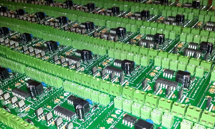
The production boards and parts arrived, a few late nights and lots of solder later, this was the result (well most of it, I couldn't fit all 55 boards in the picture);
After my experience building that number of boards I've started working with surface mount components to allow for more automation in assembly.
Next up was the installation, despite never having worked with PCB manufacturing before, and learning a huge amount there, I think I learnt nearly as much from the installation.
To keep the cost down for the farmer we re-used an IP66 rated enclosure from part of the previous electronics. While the Arduino and shield fitted well in this, by the time all the cables (eight double insulated cables) were put through glands it was a very tight fit. Small lesson learnt - you need a much bigger enclosure than you think when you're dealing with more than a couple cables.
Partly due to the enclosure size but also just due to the general amount of work required the installation proved to take quite some time. I timed it at about 30 minutes per board. As this was going to be too much time for me alone I employed the help of another local consultant. He normally does residential and commercial audio visual installations so this was a bit of a change for him but he was well suited to the job - wiring is wiring.
Another one of the things I discovered while installing the boards was that screw terminals are stronger when they are all clipped together in a long row. Having them spaced apart (as you can see in the picture) doesn't give them all the torsional strength that they could have which leads to some movement when tightening down the screws. Not a big deal but something to consider for a new revision.
After installing a few of the boards we decided to switch things on for a test. This is where things went a bit wrong and I learnt my biggest lesson of the project - do better testing. Although we tested with the actual load (the vacuum solenoid valves), we didn't test for an extended period of time. Turns out that we had an error in the board which was causing the MOSFET to not switch completely on. This resulted in heating and eventually, the destruction of the board.
So at the end of the first day things didn't seem to be going very well, we were taking longer than we thought to install the boards and the ones we had installed were trying to catch on fire. After a bit of a stressful afternoon I discovered the problem and had a patch fix. One of the traces on the PCB was not quite going to the right place, this was causing the solenoid to look like a resistor which created a voltage divider, this in nturn lowered the voltage to the gate of the MOSFET so it didn't turn fully on. Cutting one of the PCB traces and soldering a resistor in its place fixed the issue.
Although I had a fix, at this point in time we didn't have enough time to create a new set of boards, wait for them to be delivered and build them up. Instead we patched all the boards and installed them as they were. Not completely ideal but the fix was solid and there really wasn't any other choice.
I'm pleased to say that the cowshed has been running perfectly for the last few months with no failures. The farmer is happy with his system, which is running better than it ever has, and saved a bunch of money too. If anyone has any questions feel free to ask in the comments below or get in touch through the contact page.
I should work on test tools a lot more, to validate the designs really do what I think they should!
Thanks very much!
It wasn't my favourite part of the project deploying patched boards but I'm pleased to report that a year later, there have been no failures and everything is still working perfectly.
The farmer is really happy with the system and says it's made milking much easier than with the system that was there before.
Cheers,
Hadley
I was asked recently to build a "data collection" unit, which interfaced with a tablet app, for a vineyard in the middle of nowhere but I avoided the custom PCB board like the plague. In hindsight, your approach is definitely better suited to the environmental conditions/power constraints than a mini-pc.
[email protected]
thanks,
matt
Yes this is a control board which switches the vacuum solenoids for milk and pulsation etc.
Cheers,
Hadley
I'm pleased to say that the original system is still running faultlessly.
No updates unfortunately, I got part way through designing a new board but haven't had the chance to finish it off so far.
Cheers,
Hadley