
Building 100 Arduino Vacuum Pressure Gauges
Last year I installed some electronics controllers in a dairy cow shed, you can read about that project on the blog here.
After the job was completed and everything installed, the shed was tested by a milking machine testing specialist. Normally a milking plant would be tested once a year to make sure everything is running as it should. The machine tester will test various aspects of the plant to ensure that the cows are milked efficiently and without any pain or damage to their teats or udder.
As the electronics that we installed controlled the pulsation of the milking cups it was necessary to test this as it's a crucial part of the milking procedure. Happily for everyone the controllers were working well within specification and, according to the tester, better than a lot of the other commercial off the shelf systems.
The tester made a comment that if they were adjusted by 20 milliseconds then they would be running perfect timing. As it's all software this was a 10 second change to implement - not including uploading the code to the devices. It's nice to have the flexibility to change things to work exactly how you would like - not something you get with a lot of products.
I got to talking with the machine tester after that and it seems that the vacuum pressure of the milking plant is one of the most overlooked things in cow sheds. If the vacuum is out of specification then it can cause damage and discomfort to the cows, or make milking take longer than necessary. He was interested in something which can alert the worker in the cowshed to the fact that the vacuum is out.
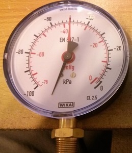
Most cowsheds have a standard manual vacuum gauge pictured right. These vacuum gauges work perfectly fine but are easy to ignore (especially if it's 5am and dark). So at his request, using what I learnt from the cowshed project I set out to make a replacement, a digital vacuum gauge.
If you read my series on Milking Cows with Arduino I learnt a few interesting things, one of those was that assembling even a relatively small number of PCBs (fifty in that case) can end up taking up quite a lot of time. Since then I've done quite a lot more PCB design and have learnt to use surface mount (SMD) technology. Using SMD means that production can be more easily automated but it's still surprisingly easy to do by hand.
Taking an idea from one of the products we stock, the SparkFun Serial Enabled 7-Segment LED Display I decided to create a similar custom Arduino board with a larger 7 segment LED display and a built in pressure sensor to measure the vacuum and display it all on one board.
Here's a picture of my hand assembled first prototype, the LED display is out of sight on the bottom of the board;
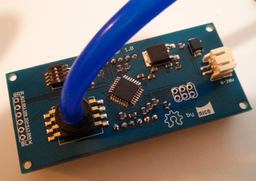
The large chip in the middle is an ATMega328P (TQFP package), the same microcontroller used on the standard Arduino board, just surface mount instead of DIP through hole. The large component that looks a bit like a digital spider on the left is a Freescale MPXV5050 pressure sensor which can sense -50 to 0 kPa (-7.25 to 0 psi) vacuum pressure. This has an easy to interface with 0-5V analog voltage output, something that is super simple to do with Arduino.
After putting this board together and doing some basic electrical testing on it with a multimeter, everything seemed to be okay, I plugged it into a power supply and no smoke came out - always a good sign! Unfortunately I couldn't do much else without programming the ATMega, and first I had to learn how to do that.
It took a little while to figure out the ins and outs of programming a bare ATMega chip. Normally with an Arduino board you would plug it into your computer using USB or an USB to TTL converter such as an FTDI cable/board, open the Arduino IDE and hit "upload". The reason you can do so is because of the Arduino bootloader that's already been programmed on there for you.
When you buy an ATMega chip in bulk they're usually blank i.e. no bootloader, to get started you need to use an ISP programmer which allows you to program the chip with your code and also program a bootloader, like the Arduino, to make uploading code in the future easier.
To program the boards I used a Pocket AVR Programmer combined with an ISP Pogo Adapter.
A neat trick I discovered was, rather than burning the bootloader and then programming the code onto the chip separately, you can upload both of those together, saving time. To do so I burned the bootloader using the ISP programmer mentioned above, switched to an FTDI breakout to upload the code from the Arduino IDE, and then used avrdude to "backup" the entire chip contents into a file on the computer. Then I could use avrdude again to upload that file to all the other boards in one step, effectively cloning the first board onto all the others.
The commands I used to clone the boards with avrdude were;
# Backup bootloader an sketch into a file
/usr/local/share/arduino-1.0.4/hardware/tools/avrdude -C/usr/local/share/arduino-1.0.4/hardware/tools/avrdude.conf -v -patmega328p -cusbtiny -Uflash:r:/home/hads/milkbar-with-bootloader.hex:i

# Upload the bootloader and sketch in one go
/usr/local/share/arduino-1.0.4/hardware/tools/avrdude -C/usr/local/share/arduino-1.0.4/hardware/tools/avrdude.conf -v -patmega328p -cusbtiny -Uflash:w:/home/hads/milkbar-with-bootloader.hex:i
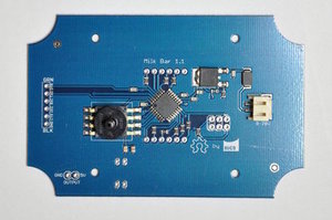
Normally when designing a PCB you'll make it as small as possible to save on the cost of the PCB material, this is what I did with the prototype above. When it came time to mount the board in an enclosure, I discovered that it would be easier to redesign the board to be slightly larger to fit and mount in a specific enclosure. Conveniently we have some great IP rated enclosures with a clear top cover so naturally I grabbed one of those off the shelf and used that. I increased the board size, had the corners routed out and located the mounting holes to match the enclosure. You can see to the right the second revision and production prototype.
I briefly mentioned earlier how surface mount technology allows more automation in assembly. While I do like assembling boards, I don't have time to manually place the components on 100 boards, that's a lot of work with tweezers. I called around a few PCB assembly businesses in New Zealand and found one who was happy to complete a small run of 100 boards for me. All that's then required is shipping the PCBs and a box of components and for a nominal fee they will put them all together and send back the completed boards.
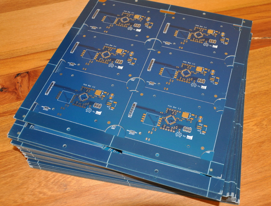
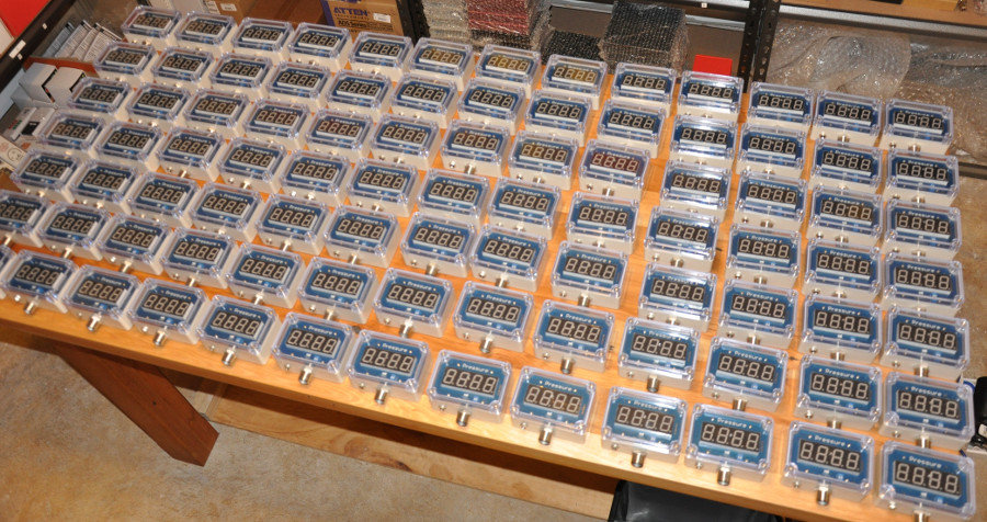
One thing that most assembly houses will require is a board in a panel, multiple copies of the board in one large board. This makes it easier to run through the robotic machines on their assembly production line. Luckily my friendly PCB supplier Hackvana offers panellised boards, here's a picture of the board panels ready to ship off for assembly.
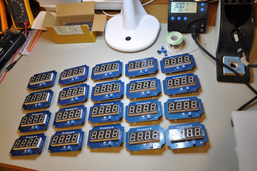
Once we received the assembled boards back at the office, we then had the rather large task of final assembly. Below you can see me just finished soldering the LED displays on to a batch of 20 boards. After that they head on over to be installed in the prepared enclosures and connected up to the air line and power connectors.
Overall, the project went really well, I didn't encounter any major issues. The main lessons learnt form this project were;
Sometimes it's better to pay someone else to do what they are good at. As much as I would love an in-house pick and place machine, forking out $20,000 plus isn't a smart option when you're doing a production run of 100 boards. When do we get to buy one? I'm not sure, maybe one day. Even when we are doing doing larger production runs there's still the learning curve of using a machine to take into consideration.
Allocate more time for programming and testing. I had plans to build a programming and testing jig to make life easier. A programming or testing jig basically allows you to clip in your PCB and have connections automatically made to upload the code and test to make sure each board is working correctly. In the end I didn't leave enough time in my project schedule to build one, it would have required designing another PCB, getting it made, making sure it works, possibly getting another revision made etc. All that would take a couple of weeks at minimum and perhaps 4-6 weeks by the time you wait for shipping. I could have pushed the delivery date back (the client wasn't actually that worried about it) but I wanted to stick with the schedule.
Designing the electronics is only a relatively small part of a project/product. The physical side of things is also a huge part of it. It took me probably just as long to sort out the enclosure, mounting standoffs, decide on the right air hose, air hose connectors, power connectors etc. There's also a lot of time involved in final assembly, drilling holes in enclosures, installing glands and things and just screwing things together.
And here's the final product;
Like most of my blog posts this has turned into a bit of a brain dump rather than anything particularly structured, I hope some useful points have come across. If there's anything specific you'd like me to go into more detail about, please feel free to leave a comment or get in touch.
Hadley
I've made several pogo-pin programming jigs. I don't make a PCB, I just drill some holes in veroboard and epoxy the pins in, using a target board to ensure pin alignment as the epoxy sets.
Please, more interesting articles!
Obviously the display is much larger than a gauge, but does it interface to a central alarm panel to alert the operator.?
Your design lends itself to many digital pressure applications.
They actually aren't really any larger, I obviously didn't include any photos which offered perspective, here's the old gauge and the early prototype;
http://nicegear.co.nz/obj/blog//milk-bar-old-vs-new.jpg
As you can see they are quite a similar size overall.
The customer who I made them for didn't request an interface back to central monitoring but I did actually include a 5V output for that just in case.
You can see the two through holes for that most clearly in the photo of the panels above, they are located in the bottom left of the individual boards.
Cheers,
Hadley
These are great! I am wondering if you might be able to build them smaller and battery powered. We would also like to change the display to a small oled.
Does the unit log the results, or just display them?
you can email me too,
[email protected]
Thanks!
No worries. I'll email you.
Cheers,
Hadley
This would fit well for a project I'm working on. We need a deeper vacuum level...up to -28inHg. I know Honeywell makes some sensors that go to that range. We'd also like to activate 4 outputs based on vacuum level ranges as opposed to a display.
0_-7 = Output 1
-7_-14 = Output 2
-14_-21 = Output 3
-21_-28 = Output 4
Can you email me so we can talk offline about this?
[email protected]
We're a bit flat out on other projects at the moment but there are contact details on the website if you want to send through some details.
Cheers,
Hadley
---
Freescale designates the two sides of the pressure sensor as the Pressure (P1) side and the Vacuum (P2) side. The Pressure (P1) side is the side containing fluorosilicone gel which protects the die from harsh media. The MPX pressure sensor is designed to operate with positive differential pressure applied, P1 > P2.
The Pressure (P1) side may be identified by using the table below
---
It seems you are using the wrong port, thus there is no guarantee that the sensor do not get damaged.
I have been making my own own fume extractors for personal use and now as a community we are working on best design for more professional grade model that gives us features found on units like hakko.
The only feature ive yet to incorporate is the pressure check and shutoff relay for replacing filters.
Have you ever considered how your design could be used in applications such as this.
Your boards look amazing! I am currently trying to use a MPXV6115V for a one off personal project. As I am new to both circuitry and Arduino I am not confident with my wiring. Is there anyway you may be able to send me diagram, or drawing of how your pressure sensor is wired (what kind of capacitors and resistors you have used)?
Thanks very much :)
It's actually a really simple circuit. Both the sensor and the Arduino (328P) are 5V analog so you can just hook the VS pin on the sensor directly to an analogue input pin on the MCU.
Cheers,
Hadley
I was just going through the data sheet for the MPXV5050 and it shows it measures from 0-50kPa. Your write up shows the reverse, that is, -50kPa-0. How did you do it ?
There are a few different models of the MPXV5050, some are designed for positive pressure, some for negative.
Cheers,
Hadley
Currently available NPWT pumps cost over $2,000!!! I had one rented from a medical supply house and an 18 inch long incision was healed completely in less than 4 weeks! I had a hip replacement. I would LOVE to make these for instances where war or other major catastrophes can help injured people heal faster.
One question... if the Freescale MPXV5050 is a PRESSURE sensor, does it also register NEGATIVE pressure (vacuum)? Typically a NPWT pump is set to around -110 mmHg (or -.146 BAR or -2.127 PSI). Thanks for any help! email me if you post your answer here on your blog [email protected]
I figure if I used new Atmel chips and program as you did with bootloader and code copied from one prototype, it would be very quick to mass produce and the cost would be, roughly about $30 per board. That is amazing. The Doctor said he can find donors to buy the parts. Thank you for designing such a wonderful board!
Kind Regards,
John
u can email me at
[email protected]