
Milking Cows with Arduino - Part 2
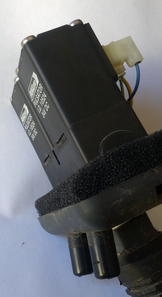
This is a follow up to part 1, the introduction. This post will talk about the electronics we designed and built. To the right you can see a picture of one of the air solenoids that we needed to drive.
First things first I built up a prototype controller. To get going as quickly as possible I used some off the shelf breakout boards from the store. Paired with a Freetronics Eleven I used a Prototyping shield, four Freetronics N-MOSFET Driver Modules, a couple of rectifier diodes and a birds nest of Hook Up Wire. I didn't get a picture of the set up but you're not missing much - it wasn't that pretty anyway.
I took the prototype electronics down to the dairy shed, plugged it in to a power supply, wired up a couple of buttons to act as inputs and wired up the vacuum solenoids to the MOSFETs. It worked - a good start! The next stage was back home, designing the actual PCB to use in the installation.
Although I am competent with basic electronics theory and know how to draw a circuit I've never designed or built a PCB before, so everything was a little new to me at this point. I opened up Eagle CAD - a PCB design program - and quickly decided that I was out of my depth. With no experience and a 2 month time frame for completion now was not the time to be learning how to design a PCB.
As I mentioned last time I enlisted the help of hairy.geek.nz, after he agreed to help I sent through a photo of a rough drawing I made with a pen and paper. Quickly I received back a picture of a PCB ready to be sent off to a board factory to be made. A couple of emails back and forth later and I did just that - sent the boards off to Mitch from hackvana.com.
There are loads of prototype PCB services out there to choose from but Mitch at Hackvana does a lot to support people creating open source hardware, his prices are great, and the turn around is good and quick. About 10 days after sending the design through to Hackvana I had a set of 5 prototype boards in my hand. I built a couple up and took them down to the farm (about 30 minutes drive).
When I got down to the farm ready to hook up my shiny new board I was quite excited. I pulled out my multimeter to check there was power before wiring things up to the shed's power supply and that is where I ran into the first issue - the shed runs on 24 volts, which the Arduino can't handle as a direct input. Originally when I talked to the farmer he had told me it was all 12 volts. First lesson learnt - don't rely on provided information, test things yourself.
We worked around that for the moment to see if the everything else with the electronics (basic program, inputs and MOSFET outputs) was working - which it was. So at the end of the day, some good points and some bad. Back home to work on a new board revision.
I talked to hairy.geek.nz again and decided that the best solution considering the time frame we had to work with was adding an off the shelf switching regulator to the existing design. It was rated to convert 24V to 9V, and then let the Arduino regulator convert the 9V to 5V as it normally does. He quickly sent through a new board layout which I sent through to Hackvana for another set of prototypes.
I think that's enough for this instalment so I'll leave it there. Next time I'll talk about the production of the boards which I didn't manage to get to this time and hopefully the installation. Any questions so far? Please feel free to ask in the comments.