Holiday Opening Hours 2013
Thank you all our fantastic customers for another stupendous year! We had our 10,000 order not long ago and well on our way again at nearly 12,000. Merry Christmas and Happy New Year to you all.
We are a family business and think it's important to spend the holidays with family. Our office will be closed from Friday 20th of December, the website will of course still be accepting orders but dispatch will be delayed until we reopen on Monday 6th January.
If you have any urgent requirements feel free to email. I (Hadley) will be sporadically checking emails and may be able to respond during the holidays.
All the best to you and yours for the holidays, enjoy yourselves and stay safe.
Cheers!
We're Moving!
We need more room. This Friday the 6th December we're moving offices. Please excuse us if we're slow to reply to emails on Thursday and Friday.
This also means that any orders placed after 3pm Thursday afternoon won't be shipped until Monday December 9th. Our apologies for the inconvenience.
Building 100 Arduino Vacuum Pressure Gauges
Last year I installed some electronics controllers in a dairy cow shed, you can read about that project on the blog here.
After the job was completed and everything installed, the shed was tested by a milking machine testing specialist. Normally a milking plant would be tested once a year to make sure everything is running as it should. The machine tester will test various aspects of the plant to ensure that the cows are milked efficiently and without any pain or damage to their teats or udder.
As the electronics that we installed controlled the pulsation of the milking cups it was necessary to test this as it's a crucial part of the milking procedure. Happily for everyone the controllers were working well within specification and, according to the tester, better than a lot of the other commercial off the shelf systems.
The tester made a comment that if they were adjusted by 20 milliseconds then they would be running perfect timing. As it's all software this was a 10 second change to implement - not including uploading the code to the devices. It's nice to have the flexibility to change things to work exactly how you would like - not something you get with a lot of products.
I got to talking with the machine tester after that and it seems that the vacuum pressure of the milking plant is one of the most overlooked things in cow sheds. If the vacuum is out of specification then it can cause damage and discomfort to the cows, or make milking take longer than necessary. He was interested in something which can alert the worker in the cowshed to the fact that the vacuum is out.
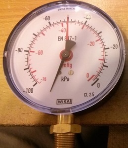
Most cowsheds have a standard manual vacuum gauge pictured right. These vacuum gauges work perfectly fine but are easy to ignore (especially if it's 5am and dark). So at his request, using what I learnt from the cowshed project I set out to make a replacement, a digital vacuum gauge.
If you read my series on Milking Cows with Arduino I learnt a few interesting things, one of those was that assembling even a relatively small number of PCBs (fifty in that case) can end up taking up quite a lot of time. Since then I've done quite a lot more PCB design and have learnt to use surface mount (SMD) technology. Using SMD means that production can be more easily automated but it's still surprisingly easy to do by hand.
Taking an idea from one of the products we stock, the SparkFun Serial Enabled 7-Segment LED Display I decided to create a similar custom Arduino board with a larger 7 segment LED display and a built in pressure sensor to measure the vacuum and display it all on one board.
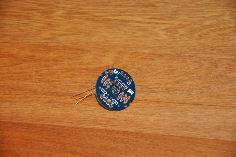
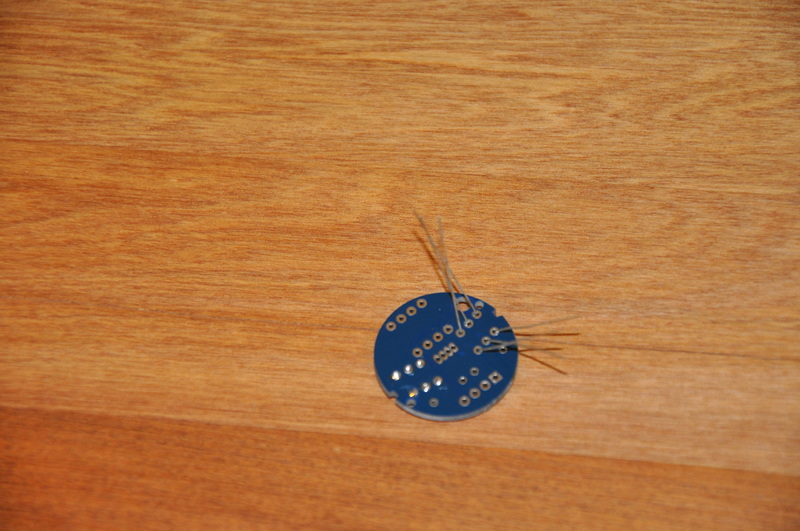
Here's a picture of my hand assembled first prototype, the LED display is out of sight on the bottom of the board;
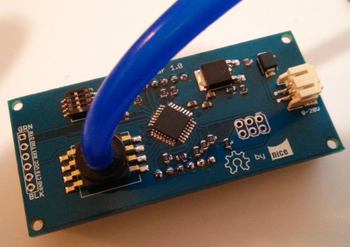
The large chip in the middle is an ATMega328P (TQFP package), the same microcontroller used on the standard Arduino board, just surface mount instead of DIP through hole. The large component that looks a bit like a digital spider on the left is a Freescale MPXV5050 pressure sensor which can sense -50 to 0 kPa (-7.25 to 0 psi) vacuum pressure. This has an easy to interface with 0-5V analog voltage output, something that is super simple to do with Arduino.
After putting this board together and doing some basic electrical testing on it with a multimeter, everything seemed to be okay, I plugged it into a power supply and no smoke came out - always a good sign! Unfortunately I couldn't do much else without programming the ATMega, and first I had to learn how to do that.
It took a little while to figure out the ins and outs of programming a bare ATMega chip. Normally with an Arduino board you would plug it into your computer using USB or an USB to TTL converter such as an FTDI cable/board, open the Arduino IDE and hit "upload". The reason you can do so is because of the Arduino bootloader that's already been programmed on there for you.
When you buy an ATMega chip in bulk they're usually blank i.e. no bootloader, to get started you need to use an ISP programmer which allows you to program the chip with your code and also program a bootloader, like the Arduino, to make uploading code in the future easier.
To program the boards I used a Pocket AVR Programmer combined with an ISP Pogo Adapter.
A neat trick I discovered was, rather than burning the bootloader and then programming the code onto the chip separately, you can upload both of those together, saving time. To do so I burned the bootloader using the ISP programmer mentioned above, switched to an FTDI breakout to upload the code from the Arduino IDE, and then used avrdude to "backup" the entire chip contents into a file on the computer. Then I could use avrdude again to upload that file to all the other boards in one step, effectively cloning the first board onto all the others.
The commands I used to clone the boards with avrdude were;
# Backup bootloader an sketch into a file
/usr/local/share/arduino-1.0.4/hardware/tools/avrdude -C/usr/local/share/arduino-1.0.4/hardware/tools/avrdude.conf -v -patmega328p -cusbtiny -Uflash:r:/home/hads/milkbar-with-bootloader.hex:i

# Upload the bootloader and sketch in one go
/usr/local/share/arduino-1.0.4/hardware/tools/avrdude -C/usr/local/share/arduino-1.0.4/hardware/tools/avrdude.conf -v -patmega328p -cusbtiny -Uflash:w:/home/hads/milkbar-with-bootloader.hex:i
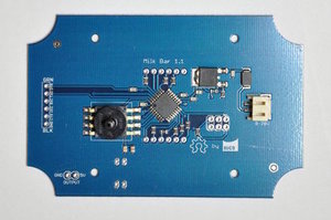
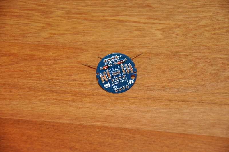
Normally when designing a PCB you'll make it as small as possible to save on the cost of the PCB material, this is what I did with the prototype above. When it came time to mount the board in an enclosure, I discovered that it would be easier to redesign the board to be slightly larger to fit and mount in a specific enclosure. Conveniently we have some great IP rated enclosures with a clear top cover so naturally I grabbed one of those off the shelf and used that. I increased the board size, had the corners routed out and located the mounting holes to match the enclosure. You can see to the right the second revision and production prototype.
I briefly mentioned earlier how surface mount technology allows more automation in assembly. While I do like assembling boards, I don't have time to manually place the components on 100 boards, that's a lot of work with tweezers. I called around a few PCB assembly businesses in New Zealand and found one who was happy to complete a small run of 100 boards for me. All that's then required is shipping the PCBs and a box of components and for a nominal fee they will put them all together and send back the completed boards.
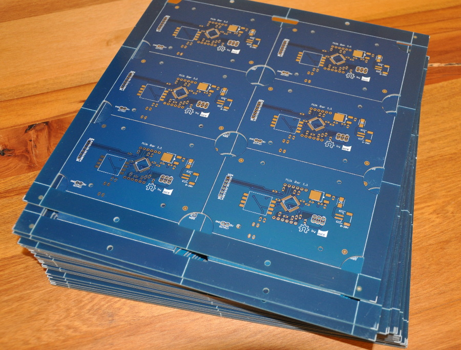
One thing that most assembly houses will require is a board in a panel, multiple copies of the board in one large board. This makes it easier to run through the robotic machines on their assembly production line. Luckily my friendly PCB supplier Hackvana offers panellised boards, here's a picture of the board panels ready to ship off for assembly.
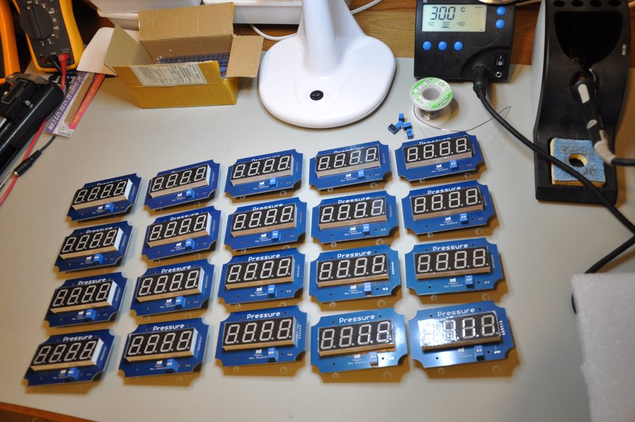
Once we received the assembled boards back at the office, we then had the rather large task of final assembly. Below you can see me just finished soldering the LED displays on to a batch of 20 boards. After that they head on over to be installed in the prepared enclosures and connected up to the air line and power connectors.
Overall, the project went really well, I didn't encounter any major issues. The main lessons learnt form this project were;
Sometimes it's better to pay someone else to do what they are good at. As much as I would love an in-house pick and place machine, forking out $20,000 plus isn't a smart option when you're doing a production run of 100 boards. When do we get to buy one? I'm not sure, maybe one day. Even when we are doing doing larger production runs there's still the learning curve of using a machine to take into consideration.
Allocate more time for programming and testing. I had plans to build a programming and testing jig to make life easier. A programming or testing jig basically allows you to clip in your PCB and have connections automatically made to upload the code and test to make sure each board is working correctly. In the end I didn't leave enough time in my project schedule to build one, it would have required designing another PCB, getting it made, making sure it works, possibly getting another revision made etc. All that would take a couple of weeks at minimum and perhaps 4-6 weeks by the time you wait for shipping. I could have pushed the delivery date back (the client wasn't actually that worried about it) but I wanted to stick with the schedule.
Designing the electronics is only a relatively small part of a project/product. The physical side of things is also a huge part of it. It took me probably just as long to sort out the enclosure, mounting standoffs, decide on the right air hose, air hose connectors, power connectors etc. There's also a lot of time involved in final assembly, drilling holes in enclosures, installing glands and things and just screwing things together.
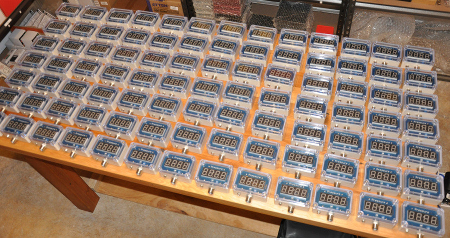
And here's the final product;
Like most of my blog posts this has turned into a bit of a brain dump rather than anything particularly structured, I hope some useful points have come across. If there's anything specific you'd like me to go into more detail about, please feel free to leave a comment or get in touch.
Hadley
Raspberry Pi Timelapse Camera Rig
 A couple of weeks ago I was asked to set up a time-lapse camera rig to take a medium term timelapse video - 4-6 weeks worth of footage. The trick was that I only had a couple days notice and no budget (it's for a charity event). Since I had to work with what was available on hand here my immediate thought was a Raspberry Pi with a Raspberry Pi Camera Module.
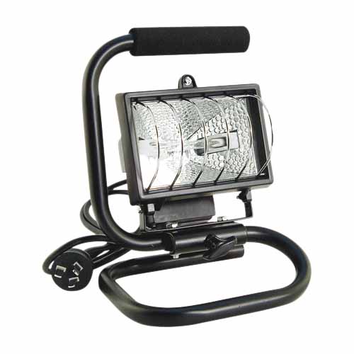
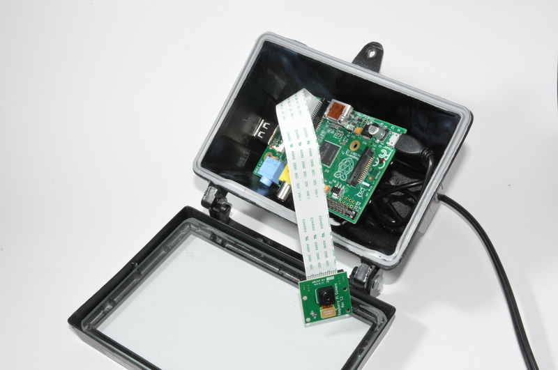
To use as an easily mountable weatherproof enclosure with a glass front for the camera I picked up a cheap halogen work light from a local hardware store. Quite cost effective at $14. After removing the handle and all of the interior parts, there's enough room for a Raspberry Pi, camera board and USB power supply.
As the time-lapse set up was going to be mounted into a caravan it needed to run on 12V, an easy way to do so was to use a Cigarette Lighter USB power supply, that way everything was "plug and play" with a standard Micro USB Cable.
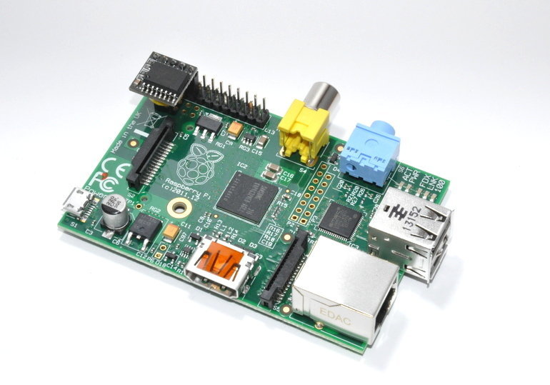
A 12V lead acid battery (standard car battery in this case, donated by another sponsor) was procured to power the rig. To decrease the power usage I switched to a Raspberry Pi Model A, which due to the fact that it has no Ethernet controller, uses less power. Measured with the bench power supply here about 50mA less. The Model B Raspberry Pi with camera etc. used around 120mA, the Model A version only used around 70mA, a significant difference when running on battery power.
Not shown installed in the picture (it was taken half way through set up) is one of our High Precision Real Time Clock (RTC) Modules for Raspberry Pi - since this rig isn't connected to the Internet it requires an external clock to keep accurate time for the image filenames. This will make things much easier to deal with when it comes to creating the video.
The original plan was to install a tiny 32GB USB drive for the images, unfortunately it didn't quite fit, very close but not quite. It would have been fine if we had one of the Low-profile microSD card adapters in stock but unfortunately we had run out. I ended up just using a 32GB microSD card for the operating system and the storage. It will fill up at some stage if it's not tended to. There's enough space for around 3-4 weeks worth of images taken once per minute.
The software side of things was very simple. Install Raspbian, enable the camera module, set up the RTC, add a cron job to save the images from the camera and that's it;
#!/bin/bash

directory=/media/usb0
filename=image-$(date +"%Y-%m-%dT%H%M%S").jpg

raspistill -o $directory/$filename -w 1920 -h 1080
And below you see the final result, the USB power supply is mounted behind the Raspberry Pi board, the camera was stuck to the glass with some tape and the Pi itself held in place with a small piece of foam wedged against the glass.
Using an I2C Real Time Clock (RTC) with a Raspberry Pi
Updated instructions for newer Pi's over here.
Unlike most computers the Raspberry Pi doesn't contain a Real Time Clock (RTC), we assume it was left out of the design to save space and/or money. A RTC is a coin cell battery powered clock which keeps accurate time, even when the computer is powered off. Without one, the Raspberry Pi isn't capable of keeping time by itself.
If you're using a Pi Model B with an Internet connection then you can get the time from the Internet using Network Time Protocol (NTP), however if you're using a Model A or just don't have a network connection, then you'll need an RTC to keep time.
We've found a simple to use RTC module for the Raspberry Pi with the Dallas DS3231 I2C RTC chip which is also a bunch more accurate than the commonly used DS1307 chip. It's also tiny, and fits right on the Pi's GPIO header (seen top left of the image).
Here's the basic steps you need to get the Pi RTC Module going on the latest Raspbian distribution you can download from the Raspberry Pi Foundation's website.
# Remove the module blacklist entry so it can be loaded on boot
sudo sed -i 's/blacklist i2c-bcm2708/#blacklist i2c-bcm2708/' /etc/modprobe.d/raspi-blacklist.conf
# Load the module now
sudo modprobe i2c-bcm2708
# Notify Linux of the Dallas RTC device
echo ds1307 0x68 | sudo tee /sys/class/i2c-adapter/i2c-1/new_device
# Test whether Linux can see our RTC module.
sudo hwclock
That's it! You can also add the i2c initialisation command to rc.local which means it will be run at every boot up;
# Add the RTC device on boot
sudo sed -i 's#^exit 0$#echo ds1307 0x68 > /sys/class/i2c-adapter/i2c-1/new_device#' /etc/rc.local
echo exit 0 | sudo tee -a /etc/rc.local
This doesn't cover automatically setting the clock on boot and but you can do so by adding another line (above exit 0) to rc.local with;
hwclock -s
Testing Products with Products
We like to have quality products. Right from when we began back in 2005/06 that was one of the core ideas, to sell quality hardware which was hard to find locally. Selling crap gear is no fun for anyone; the customer gets a rude shock when whatever they purchased arrives and is big let down. We don't make any money because people return the bad products to us for refunds. Basically everybody is unhappy and we go out of business.
Back then it was quite easy, back then I could count on one had the manufacturers of the products we sold and sales were small enough for me (Hadley) to spend plenty of time on each one. Fast forward to 2013 and these days with the large order volume, wide variety of products we sell and sources we get them from, it's not quite so easy. It's important for me to be vigilant and make sure that we're not turning into just another online store selling bulk, cheap low quality goods.
Of course all of this isn't to say that we don't get faulty products, of course we do. There's always going to be a few defective products and if you start selling in a reasonable volume then this can start to mount up quickly if you're not careful. Thankfully selling the products we do means that there's usually sometime useful lying around to make testing things out easier.
We recently had a customer having issues with a 4 port USB wall charger. This is an interesting case as I am pretty confident that the chargers are decent quality. Like most products I had tested them myself before they were listed for sale. We arranged a return of the charger to check it out here.
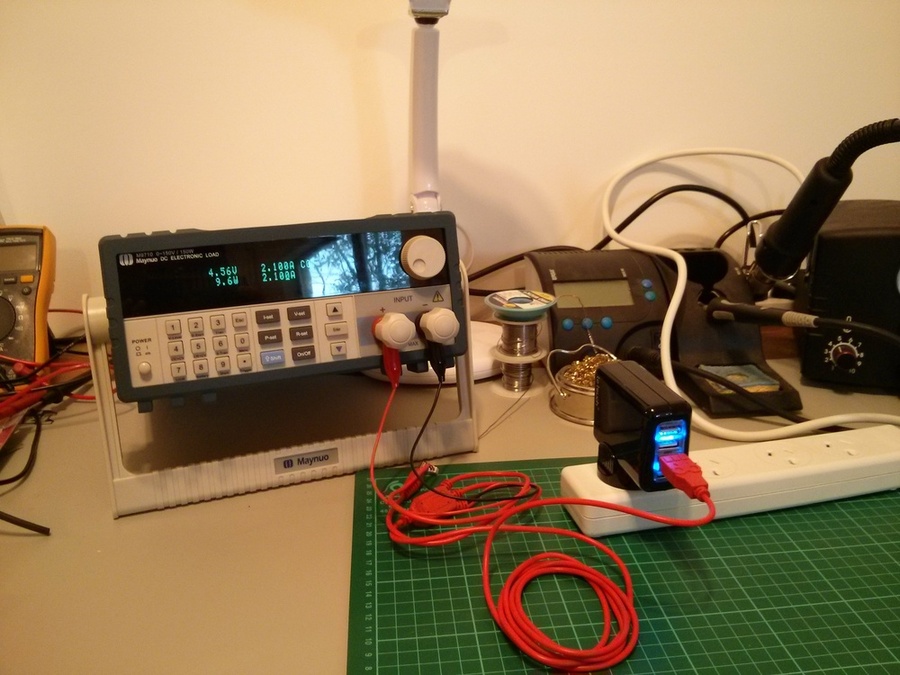
You can see a picture of me testing it above with one of my favourite toys, an electronic DC load. You plug into that the load you want to simulate - in this case 2.1A which is the rated specification of the USB charger - hook up the device and press go. So I didn't have to cut up another USB cable I used another handy product, the SparkFun Hydra Cable which plugs into a USB port and gives you various outputs such as banana plugs I used here..
If you ignore the reflection of trees out my window you can see on the pretty display of the electronic load 2.1A at 4.56V. This is within the USB voltage specification and shows the adapter can supply what it says it does. I left this running for an hour or so, it did get a little warm but seemed perfectly stable. You'll note it's not quite 5V that USB is meant to be. This is a combination of droop from the charger under load and voltage drop over the length of the USB cable which is normal.
So what was the problem the customer was having? Turns out they were trying to draw quite a bit more than the USB adapter is rated for. They were wanting to charge two iPads and two iPhones all at the same time. Looking at the specifications these can draw up to 2A each so that is possible 8A total, four times more than the charger is capable of. At that load the voltage would drop and it may stop charging completely. I've since added a clarification to the product page so others don't make the same mistake in the future.
10000th Order Milestone
At exactly 8am yesterday (Thursday) the nicegear web store reached quite a neat milestone, order #10000 was placed. Matt from Christchurch ordered a Raspberry Pi. Like most orders this was shipped out the same day, unlike most orders and because it was such a special number we gave it away for free.
I was contemplating how fast we've progressed to that number and what the interval timing of it was so I jumped into the database to have a look with this command;
SELECT id, created FROM orders WHERE id % 1000 = 0 ORDER BY id;
After pasting the results into LibreOffice Calc (a spreadsheet app) I was given the following graph;
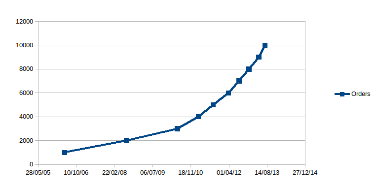
I'm really stoked with the performance of our little operation run out of good old Timaru, New Zealand.
Needless to say I'm quite proud of what we've achieved over the years (which seem to have just flown past!) but I mostly wanted to put this in writing to say a huge thanks to all of you, our customers. We don't advertise, pretty much the only way we get the amount of business we do is through fantastic folks such as yourselves who tell a friend or family member about us.
Thank you all very much.
- Hadley Rich
Introducing the OrBlink, a USB connected RGB LED Orb
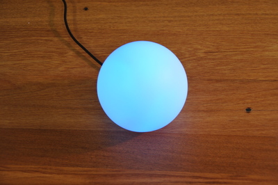 Introducing the OrBlink, a USB connected RGB LED Orb, plug it into your computer (any will do, no drivers required) and use it to indicate whatever you can imagine.
I (Hadley) came up with the idea for making one in early 2013 when our Mr3, our 3 year old got confused about when to get out of bed. Daylight savings had ended and it was quite dark in the mornings, this meant Mr3 didn't know if it was really early or not.
Mr3 already has a low power computer in his room which we use to play music for him so I thought I could leverage that for power and logic to control an RGB (Red Green Blue) LED and show him when it was an okay time to get up.
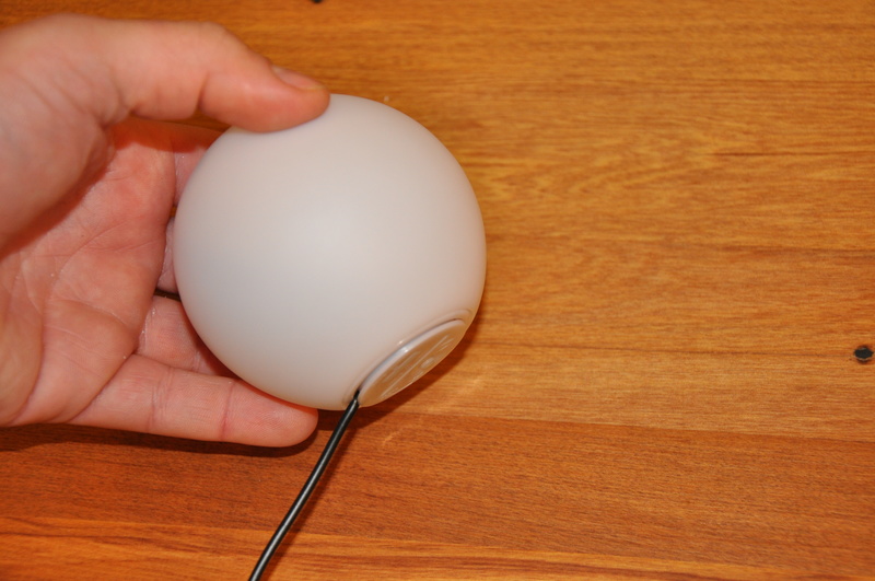
I wanted something nice and soft and diffused so it didn't cast shadows in the room, kids don't tend to like that much. So I hunted around and found some nice little plastic orbs or spheres, about 80mm in diameter. These were designed as a color changing LED to start with, but battery powered and not controllable.
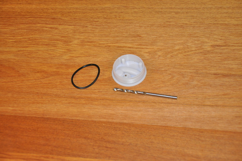
I purchased up a few orbs and when they arrived I pulled one apart. There was a small circuit board in there with a couple of cheap batteries and LEDs, conveniently held together with screws for easy removal.
This was the time I turned to the Internet and typed "avr usb rgb led" into DuckDuckGo (which is a great alternative to Google but that's another story). The "avr" in there is for a type of microcontroller from Atmel, much the same as what's used in Arduino Boards, the rest of the search is pretty self explanatory. The first link in my search was to some code written and kindly published by some bloke called Dave back in 2009 who built something pretty much exactly the same, thanks Dave!
With that information found I knew pretty much what I needed to do, a simple circuit based on the ATTiny85, a RGB LED and a few other passive components. I put together an ugly little prototype on a cut down square protoboard (we were all out of round protoboards) with bits I found around the workshop hanging off it left right and center. Ugly it may have been but it worked first try which is always a bonus.
Using my newly found interest in designing custom printed circuit boards (PCBs) I set out and created a replacement PCB that would fit in the existing little base of the orb. Here's the schematic I came up with.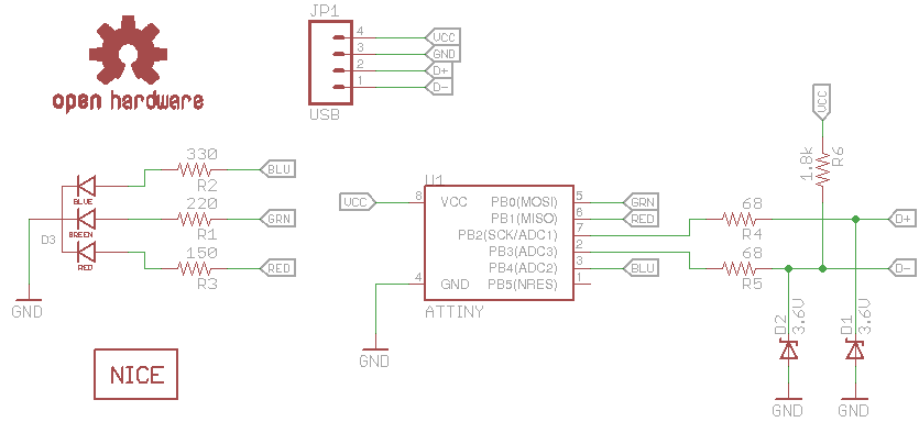
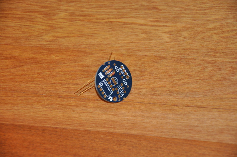
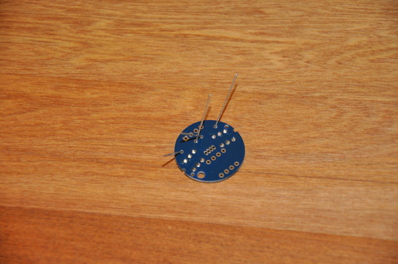
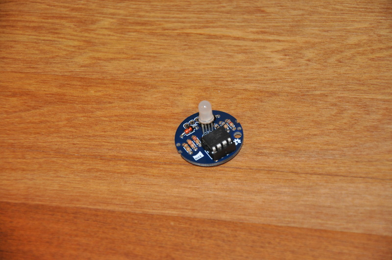
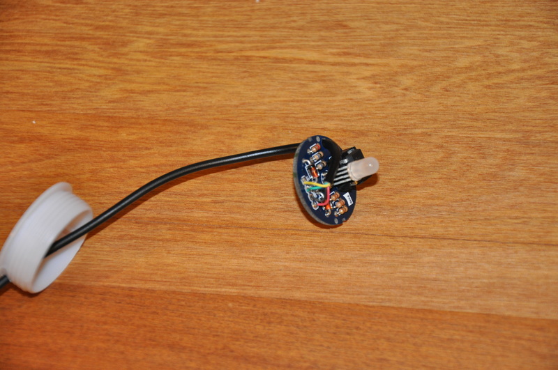
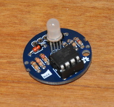 I sent my board design off to Hackvana, the friendly custom PCB making service, a short time later I had some prototypes in my hand. Here's what they look like, assembled with all the through hole components, but not yet mounted in the orb.
Looking at the little built up PCB made me think that perhaps other people might like to build one of their own, and it fits in pretty nicely with all the other stuff we sell, so I decided to make up a bunch of kits and put them up for sale on the website here.
There are a few other very similar products around all created recently such as the Blink(1) by ThingM and the BlinkStick by Agile Innovative. They are all based on the same basic hardware and principle, most of them are based on the same source code too. I think ours is neat since we made it of course, and it comes in a neat little Orb which looks great sitting on a table.
All the source code for the OrBlink is available on GitHub, including the hardware design files (created in Eagle), the firmware to run on the ATTiny85 firmware (modified from Dave's code, which is originally based on a V-USB example), a C command line program to control the OrBlink (again based on code by Dave), and some Python code written by me based on pyusb.
Why not pick up an OrBlink Kit today, learn some new or practice your existing soldering skills, and end up with a neat useful little gadget at the end of it.
Have you got any questions or comments? Want us to consider stocking pre-assembled ones? Anything else? Let us know in the comments below or get in contact directly (especially if our comment form spam protection is being hyper active again).
All the best - Hadley
Building the OrBlink USB RGB LED
This is the guide to building the OrBlink USB RGB LED Kit.
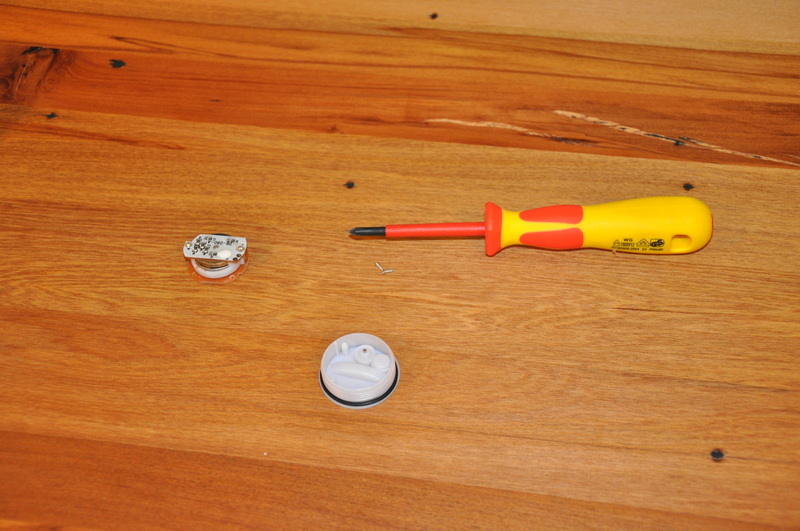
You'll need a few tools which aren't included in the kit. To assemble the board you'll need a soldering iron, some solder, some wire strippers and some small wire cutters. To pull apart and put together the orb you'll need a large flat head screwdriver (or a coin), a small phillips screwdriver, and a drill or something else to make a hole. Other useful items are a helping hand tool to hold the board while you solder which will make things much easier and a good multimeter to test your joints but they aren't strictly necessary.
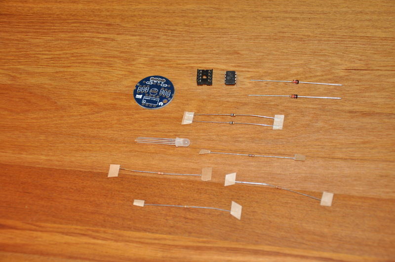
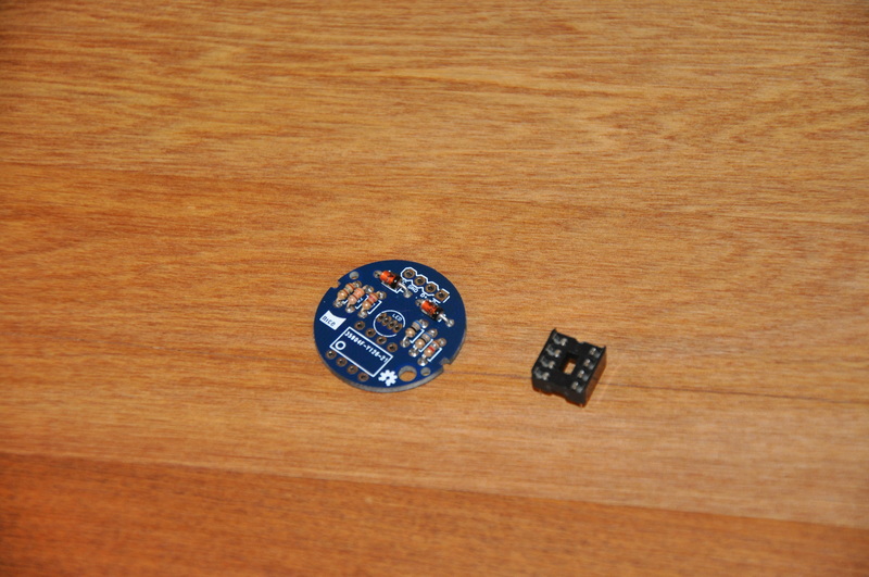
Step 1. Check the parts, you should have the following;
- 1 Orb
- 1 OrBlink PCB
- 1 Pre-programmed ATTiny85 microcontroller
- 1 DIP socket for the microcontroller
- 1 RGB LED
- 2 Zener diodes (D1,D2)
- 1 220 ohm resistor (R1 - red red brown)
- 1 330 ohm resistor (R2 - orange orange brown)
- 1 150 ohm resistor (R3 - brown green brown)
- 2 68 ohm resistors (R4,R5 - blue grey black)
- 1 1.8k ohm resistor (R6 - brown grey red)
- 1 USB Cable
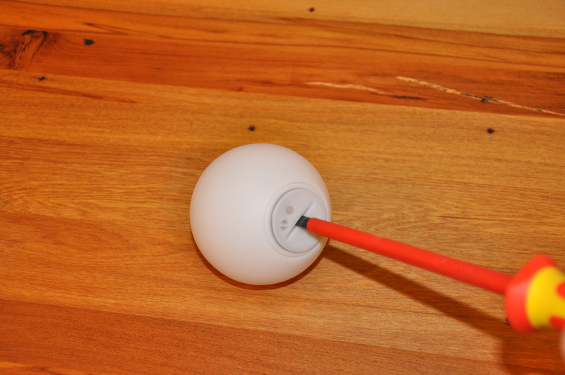
Step 2. Remove the base of the orb, it's best to use a coin here or a really big flat head screwdriver - they tend to be pretty tight.
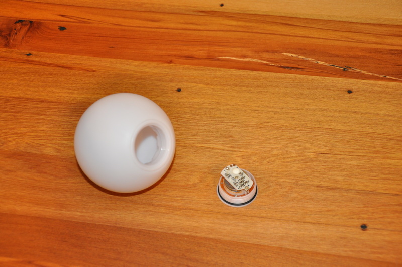
Step 3. Remove the old PCB and battery assembly from the orb. Save the screws, do whatever you like with the old PCB.
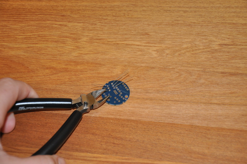
Step 4. Install R1 (220 ohms, red red brown), R2 (330 ohms, orange orange brown) and R3 (150 ohms, brown green brown). Bend the legs, insert them through the holes and bend as per the picture to hold them in while you solder.

Step 5. Solder the resistors by touching each lead with the soldering iron a piece of solder lightly. Trim off the leads with your flush cutters.
Step 6. Install R4, R5 (68 ohm blue grey black) and R6 (1.8k ohm brown grey red) using the same technique as above.
Step 7. Install the zener diodes using the same technique as the resistors above. Be careful as diodes are polarised - you need to install the stripe to match the stripe on the PCB.
Step 8. Solder in the DIP socket, orient it so that the end with the notch cut out is at the same end as the small circle pin 1 marker on the PCB.

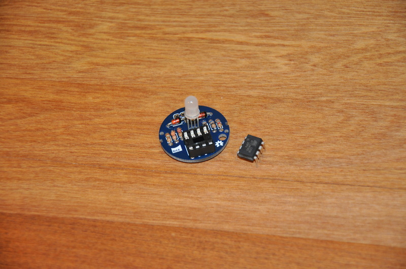
Step 8. Place the RGB LED through the PCB, leave it sticking up around 15mm so it doesn't cast shadows of the other components on the inside of the orb. Orient the LED so the flat side of the plastic is facing towards R4.

Step 9. Solder in the LED. Use a little solder here as the pads are quite close together and may bridge if you use too much.
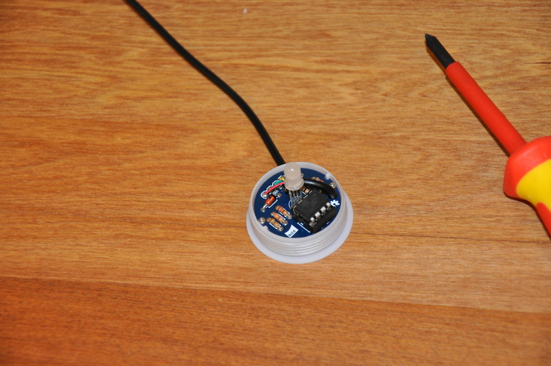
Step 10. Install the ATTiny85 microcontroller, if you need to you can bend the legs in slightly by pressing down on a flat surface. The end with the little round impression on the top goes at the end of the socket with the notch in it.
Step 11. That's the PCB assembly completed, well done! Now you just need to put the orb back together.
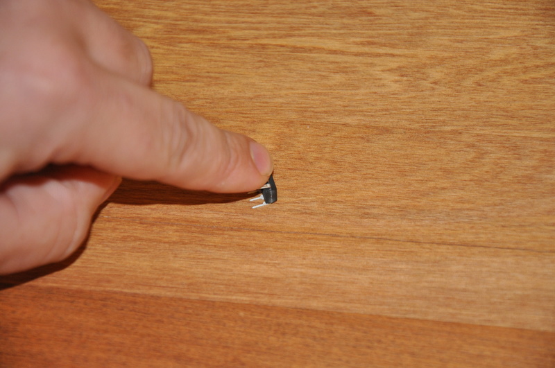
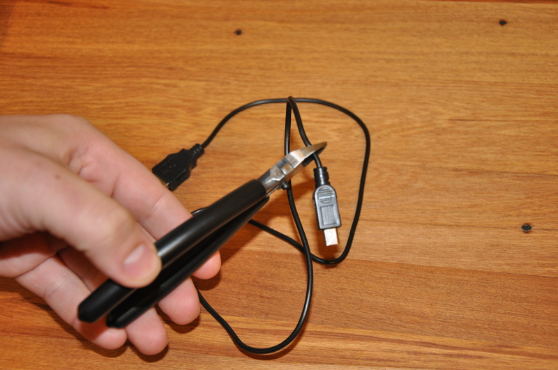
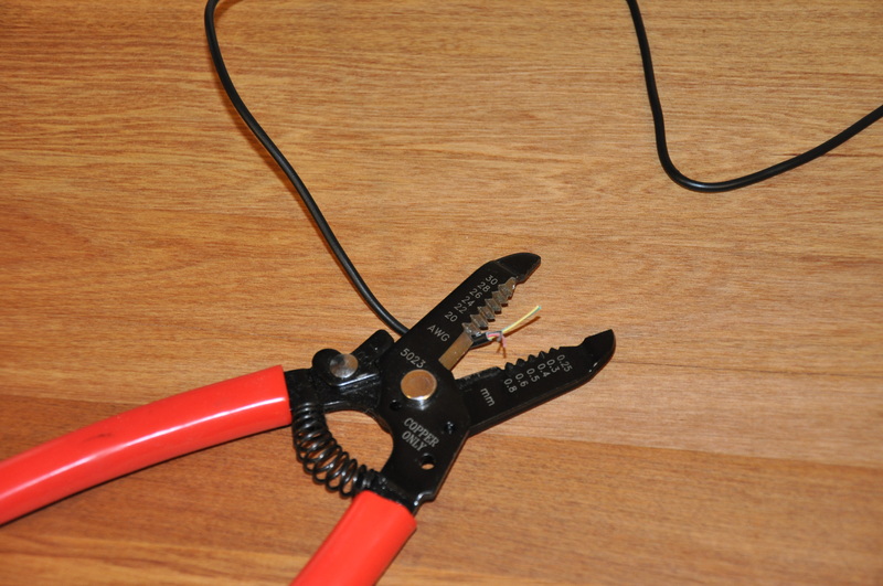
Step 12. Cut the end off the USB cable (not the one that plugs into the computer) and strip the large outer insulation, then the four smaller wires inside that. You only need a short amount os the inner insulation stripped.
Step 13. Remove the rubber gasket from around the orb base and drill a small hole in the very bottom of the thread. It needs to be big enough to fit the USB cable, around 3mm.
Step 14. Insert the stripped end of the cable through the orb base and the large hole in the PCB.
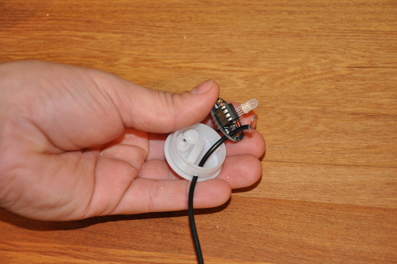
Step 15. Solder the stripped wires into the PCB, most USB cables use standard colors. Red for 5V, black for ground, green for D+ and yellow for D- match them up to the labels on the PCB.
Step 16. Screw the newly completed OrBlink PCB into the existing holes in the orb base with the screws you saved from the start.
Step 17. Screw the base back on to the orb, plug the OrBlink into your computer and start making colors!
If you're new to soldering you might want to test the USB cable to make sure there aren't any shorts which may cause damage to your computers USB port. This is up to you.
Get a real MAC address for your Arduino Ethernet
There's this thing that some people like to call the "Internet of Things" (IoT), mostly this is just a fancy name for "devices that don't have a person sitting in front of them connected to the Internet". As part of that general theme, Ethernet connected Arduino projects are very popular, we use them a lot ourselves here. Most of the projects we do are connected to some sort of network.
If you've ever had more than one Arduino device with Ethernet on the same network then you will have had to deal with the issue of MAC addressing. When you've just got one one you can make one up, the good old DE:AD:BE:EF:FE:ED is popular. What happens though if you want to add another project to your network? Things stop working.
There are various solutions, we've posted a couple on this very blog, none of them are just right though.
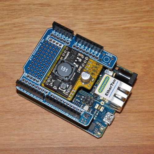
So we created a shield to solve the problem once and for all. Introducing the MAC ProtoShield - an oddly shaped shield for an Arduino which gives you an official MAC address, none of this made up stuff, no having to manually hard code one in for each Arduino.
You can see it above installed on a Freetronics EtherTen along with an 802.3af Power over Ethernet (PoE) module. That's the reason for the funny shape - you can fit one of the Freetronics PoE regulators inside the MAC ProtoShield footprint, making it easy to do tidy one cable installations.
The secret is seen in the bottom of the picture, a tiny surface mount EEPROM chip which has a built in MAC address accessible over I2C. You also get 2Kbit of extra EEPROM to play with. We've got some simple example code available to show you how to incorporate it into your next project. It's really easy and small, only 40 lines of code.
You also get a small prototyping area with power rails and if you use stackable headers it's a good solution to the problem of the Ethernet jack getting in the way of a full sized shield. Although we like to use them with the EtherTen, they also work just fine with a standard Arduino Ethernet Shield, Arduino Ethernet or anything else that supports the "r3" headers.
The board design is open source and available on GitHub if you're interested. We'd love to hear your comments or questions via the comment form below or you can contact us directly here.
Rocks
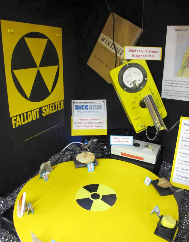
A customer of ours sent in this neat photo from the Rock & Mineral Show that they put on at the Mineral Club of Hutt Valley and Wellington.
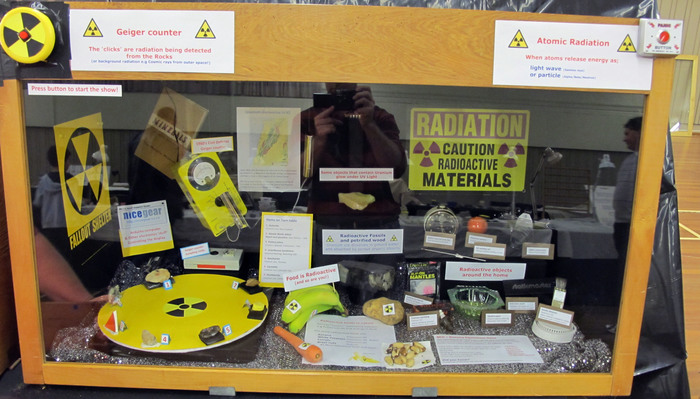
Here you can see the left hand part of the display in more detail, there's a Freetronics EtherTen controlling the turntable which moves various radioactive rocks into position under an old Geiger counter, very cool!